
 |
 |
 |
 |
 |
You are not logged in. Would you like to login?
 1 of 1
| Independent Rear Suspension Forum » CV Joints Update » 6/04/2011 7:03 am |
Sammy ... I too am very interested to see how this all comes together!
| Independent Rear Suspension Forum » CV Joints Update » 6/04/2011 7:01 am |
Sorry Daze ... not an option on this version
| Independent Rear Suspension Forum » CV Joints Update » 6/02/2011 5:32 pm |
Daze ... you are absolutely correct, I can move the parts up and down and see the results real time. It also has a variety of motors that can move the parts continuously.
| Independent Rear Suspension Forum » CV Joints Update » 6/01/2011 4:34 pm |
Using some simple trig tables ... at 5inches of travel the track width shortens up from 13.75 to 12.82 or 0.93 inches on each side.
| Independent Rear Suspension Forum » CV Joints Update » 6/01/2011 8:05 am |
I received an e-mail from Sammy with updated dimensions so I plugged them into the model and the results were VERY interesting.
The dimensions from the left edge of the block represent the distance from center of the center section. The upper and lower control arms are set parallel to the center shaft and set 6 inches apart. The cumulative distance from left to right is 23.8125 inches for both the upper and lower control arm which set the camber exactly at zero degrees. The length of the center shaft is variable based on movement up and down.
I then moved the hub to a travel position 5inches up. The camber went negative a total of 0.9 degrees and the center shaft shortened up a total of .01 inches. Very nice ... I think Sammy was looking for a 1.0 degree negative change.
Now comes the surprise
When I moved the hub to a travel position 5 inches down the camber again went negative 0.9 degrees. In our stock Jag setup the camber goes positive when the travel position goes down andthis of course is bad for handling. I have checked and double checked all of the dimensions in the model and I can't find anything wrong. It appears that Sammy has captured the best of all worlds ... CV Joints on a Jag center section and incredible camber control.
| Independent Rear Suspension Forum » Jaguar IRS spring rate again!!! » 5/21/2011 6:01 am |
I did all of the same calculations and came up with the same conclusions ... one spring should be plenty. Additionally, the QA1's I had were giving another 60 lbs of force. But when I did the mock up with one spring it clearly wasn't up to the task. I put two springs on at it sat right where I wanted it and when I jumped up and down on the rear bumper the dampening effect was not excessively stiff. Now I did use the stock springs in the stock locations plus who knows how old the springs were but I do remember thinking that the math just didn't add up to the results. I know this doesn't help with your decision making but I also know that you like all of the inputs you can get ![]()
| Independent Rear Suspension Forum » One pair of coil overs or two pairs??? » 5/21/2011 5:36 am |
I was still thinking about the twisting forces on the LCA this morning when I remembered that you designed your own sway bar configuration. I had to go back and look at the photos ... nice job by the way. That sway bar is trying to twist both of the LCA's right off the mounts. I am pretty sure that the forces from the sway bar far exceed anything a single shock is going to exert.
| Independent Rear Suspension Forum » One pair of coil overs or two pairs??? » 5/20/2011 8:04 pm |
OK ... I'll throw my two cents worth. Yes there will be forces applied to the lower control arm with only one shock mounted BUT what the LCA is going to twist ?!? steel ... really ... the only way that any motion in the LCA could exist is if the mounting points allowed that motion. I know that you are running the UHMW bearings and that pretty much eliminates any movement.
If that doesn't instill any confidence lets try this ... you are sitting at a stop light listening to your favorite tunes when suddenly a camaro pulls up next to you, he (or maybe a she) looks over at you at smiles. We all know whats going to happen ... 1st gear pedal to metal and blow the doors off that camaro. Well while that is happening the wheels are trying to rip the LCA's right off the car. I'm pretty sure that the LCA's are going to do their job and the forces imparted are going to be far greater than one little shock
One last visual .. I built custom LCA's for my IRS and I asked myself if I was going 100 MPH (I love going fast!) and had to slam on the brakes suddenly would the LCA do it's job ... I have no concerns ... but the point is if you were running stock or semi-stock in your case do you think that the forces applied during a panic stop would be greater than running one shock ???
One last thought, the LCA's were designed by Jag to handle the forces from a variety of inputs ... the shocks, I'm guessing, were designed to dampen only one force ... the up and down motion of the vehicle.
| Independent Rear Suspension Forum » Hey Joe, I took your brake fitting idea and modified it » 5/18/2011 5:59 pm |
Ahh ... the copper washer you got to love it ... nice work Daze.
| Independent Rear Suspension Forum » CV joints on jag IRS? » 5/13/2011 4:26 am |
Sure did ... been posting stuff on the forum.
Topic "CV Joints on a Jag Center Section" Last update was 5/10
| Independent Rear Suspension Forum » CV Joints on a Jag Center Section » 5/10/2011 6:31 am |
I was looking at the model and thinking about what Sammy had said in an earlier post that he was going to be using an upper control arm (UCA) to better control the camber changes. So I changed the model and started moving the control arms up and down to see what changes the camber experienced. I then recalled a photo of an IRS from TEAM321 that used an UCA. The pivot point on the UCA was quite a bid inboard from the outer hub so I started making chages to the model to see what affect this would have on camber. 
I started with UCA and LCA the same length 18" (this number is purely random just to give us some numbers). I then progressively moved the pivot point on the UCA only in increments of 1". This was done by removing 1" from the UCA and adding 1" to the hub so that camber remains at zero when the center shaft is at zero. Camber and center shaft length was recorded only at the extremes of travel +5" and -5" from zero.
LCA
/ UCA Travel Center Shaft Length Camber Change
18 / 18 5 / 5 13.65 / 13.65 -4.7 / +5.3
18 / 17 5 / 5 13.63 / 13.65 -4.9 / +5.3
18 / 16 5 / 5 13.60 / 13.65 -5.2 / +5.3
18 / 15 5 / 5 13.57 / 13.65 -5.8 / +5.3
So here are the results. As you can see changing the upper pivot point only affected camber when the center shaft is moving upwards from zero. I would have expected that any change would have affected camber throughout the entire range of movement.
Looking at the TEAM321 unit I noticed that the UCA is almost parallel with the center shaft. I am going to move the pivot point on the UCA at the center section end and see what kind of changes we get.
| Independent Rear Suspension Forum » CV Joints on a Jag Center Section » 5/06/2011 6:24 am |
And so we begin ... I received all of the measurements. Below is an image of the model. I made some changes to help us work through the variables. In its current state I have not put in any of your measurements ... and the pivot points are purely random. The model has three basic components currently and as we start locking in dimensions I will create additional components. The block on the left represents the center section. It is locked down and does not move. The center shaft moves up and down without limits and we can measure that movement from center. Right now center is defined as centershaft angle = 0 degrees. The last component is the hub carrier (if you have better teminology for this part let me know) This is where we measure the camber positive and negative and again without limits. Obviously we have to subtract the angle from 90 to get the true camber. I have added pivot points for the upper control arm but in the beginning stages is not required. The model will move the components accurately without those points attached.
The one thing to keep in mind is that SolidWorks is extremely accurate so the better job we do of putting in dimensions the better job the software will do.
I need two things to proceed forward. First the pivot points on the CV. Does the CV Joint perform similiar to the half shafts on the Jag unit? By this I mean does it attach to the outer hub so that the length does not change? Also, as the center shaft moves up and down does it allow the hub to move independently again similiar to the half shafts. I really am clueless here.
The second thing I need is some guidance on the hub carrier. The center shaft mounts in the center of the hub and I assume that the hub will mount in the center of the hub carrier. I am also guessing that the hub carrier is something you are going to make. The pivot point for the lower control
| Independent Rear Suspension Forum » hey Joe, hows is your project coming along?? n/m » 5/05/2011 6:14 pm |
Hi Daze ... project hasn't changed much from the last time we spoke. I am pretty confident that my motor will be finished up this year and then I can attack the suspension. I still check the forum almost every day ... you've created something pretty special here.
I am thinking seriously about putting an Auburn Gear in my unit. I saw the post you put up regarding the ebay sale and I was amazed how inexpensive it was. My son knows a guy who can do the install .... so what am I waiting for ??
| Independent Rear Suspension Forum » CV joints on jag IRS? » 5/05/2011 6:03 pm |
Below the picture of my 67 Mustang is a hot link to my e-mail address. jec@aitbusiness.com
There' s going to be a fair amount of trial and error with these measurements but I am confident that we can figure it out.
| Independent Rear Suspension Forum » CV joints on jag IRS? » 5/05/2011 7:16 am |
My pleasure ... should be fun.
| Independent Rear Suspension Forum » CV joints on jag IRS? » 5/05/2011 4:54 am |
Yes I did use the jag design with the LCA. I don't know as much I would like about the details of CV joints as they move through the motion of the suspension. Pivot points however are relatively easy to analyze once you know the lengths and positions. 
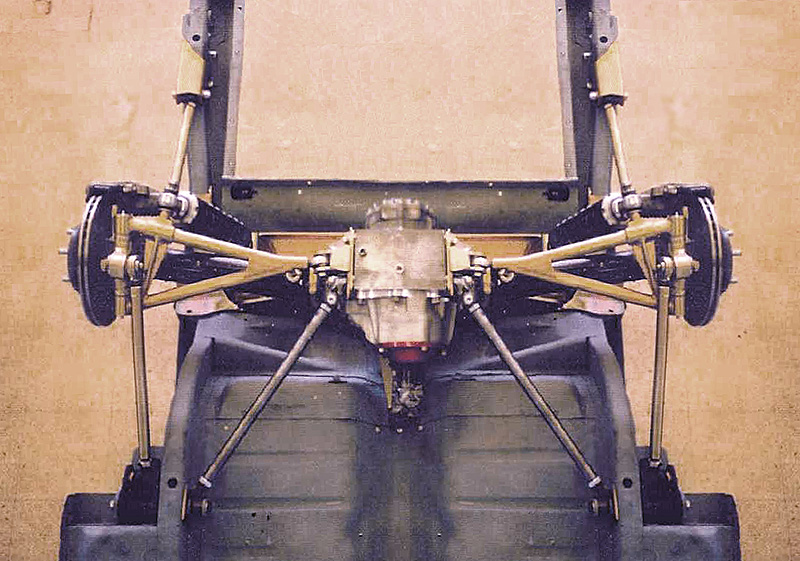
Here is the model that I used. The pivot points for the half shaft are based on the length from eye to eye and the same for the LCA. The positions are taken directly from the center section and the hub.
In your situation everything is pretty much unknown and can be set to anything you want which makes it more difficult (as you already know). A couple of things you do know however ... the overall length of the unit, the lengths of the CV, and the pivot points of the CV. Imagine that we create a new model for you (I would be happy to do that) and we start with just the CV and move it up and down 11 inches or more. Then we dial in whatever camber gains and losses you think you might like and then calculate the lengths/positions of the upper and lower control arms
With SolidWorks if there is a conflict the software will identify where it is. It will probably take several iterations and maybe a couple of changes but I am sure we can get you close to what you are looking for.
| Independent Rear Suspension Forum » CV joints on jag IRS? » 5/02/2011 4:25 pm |
Slammy, I love what you are doing with the CV's ... I did some simulations for Daze a while back using a CAD package called Solidworks. I used the stock lengths from a 69 XJ6 and calculated the camber gain through 10 degrees of travel up and 10 degrees down, then did a second calculation using Daze's length on his unit. The numbers were interesting. Starting with the half shaft at zero and camber at zero ... at 10 degrees up the camber goes to -1.83 and travels 2.54 inches. At 10 degrees down the camber goes to +0.79 and travels 3.15 inches. This is a total of 5.5 inches of travel which is half of what you are trying to get ... the camber gain at 11 inches is going to be interesting to say the least.
| Independent Rear Suspension Forum » Simple upgrade to improve an air compressor » 1/13/2011 7:52 pm |
I like the ball valve ... here's another one just because. We have the compressor in a shed and copper lines running into the garage. Of course the shed is always packed with stuff and getting to the compressor is a project in itself. So we removed the petcock and installed a piece of compressor hose into the threaded bung and then put an air nozzle on the other end of the hose. We can now take a plastic cup and point the air nozzle in the cup and fill it up with water ![]()
| Independent Rear Suspension Forum » I haven't seen any updates on every one else's projects Let us know... » 12/09/2010 6:03 pm |
Nothing new to report on the Jag project. My brother decided we needed a fill in project while we were waiting ![]()

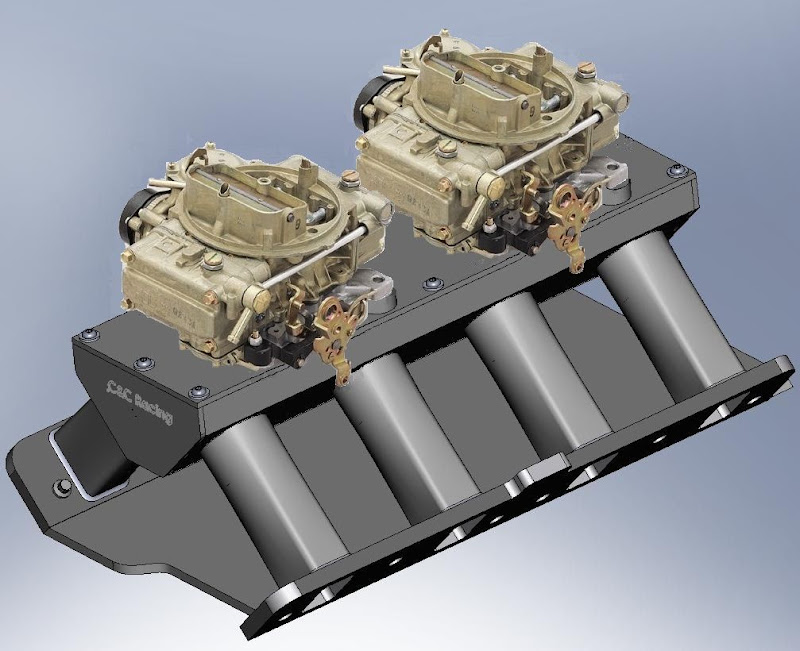
The manifold was designed in Solidworks ... the carbs are holley 390's cfm. This will be going on his 500 C.I. Cad motor. Been a really fun project !!
| Independent Rear Suspension Forum » Hey Joe, question about your brake fittings » 11/23/2010 9:50 am |
I didn't pick up on the rotors but now that you mention it ... is that a spacer block in between the caliper halves?
The power bleed idea would be pretty cool if you could hook up to one side of the e-z bleed system and open the other side. Bleed both calipers at the same time.
I'm kind of a simpleton though ... open the bleeder an let fluid run all over the place ![]()
| Independent Rear Suspension Forum » Got my swaybar half way mocked up. The end link and mounts are done. » 11/11/2010 7:56 pm |
The "Square Tap" ... simply brilliant. ![]() I like the sway bar end link bracket. It has the look like it came from the factory that way or at least should have. I see you have some more of that cage attached to the back also. I was showing my brother some of your latest photos and we are both curious if you're planning to run the stock Jag jackplate?
I like the sway bar end link bracket. It has the look like it came from the factory that way or at least should have. I see you have some more of that cage attached to the back also. I was showing my brother some of your latest photos and we are both curious if you're planning to run the stock Jag jackplate? ![]()
| Independent Rear Suspension Forum » Hey Joe, question about your brake fittings » 11/08/2010 9:50 am |
I did not use sealant on the threads. My understanding was that the bevel on the end of fitting would seat against the bottom of the caliper. Thinking about it though it makes sense to use something. We use teflon tape on the MIG welder tank and that fitting is similiar in design. Thanks!! I'm going to do it.
| Independent Rear Suspension Forum » Got my front pinion support fabbed up » 11/06/2010 5:00 am |
That picture sure does answer a lot questions! It will be interesting to see how the sway bar gets mounted.
| Independent Rear Suspension Forum » What do you think of my extremely light, fiber composite drive line??? » 11/03/2010 6:31 pm |
Very nice !! Been spending some time researching exhaust ... flow, velocity, EGT, lots to learn out there ![]()
| Independent Rear Suspension Forum » What do you think of my extremely light, fiber composite drive line??? » 11/03/2010 5:32 am |
I chuckled ... a little ![]() A little off topic but I notice you are running glasspacks with an X-pipe and side exhaust. 2 -1/4" pipe? Long tube headers? How do you like the sound?
A little off topic but I notice you are running glasspacks with an X-pipe and side exhaust. 2 -1/4" pipe? Long tube headers? How do you like the sound?
| Independent Rear Suspension Forum » Hey Joe, my pinion support cage part mods inspired by you » 10/30/2010 5:28 am |
We didn't have the MIG welder at that time so gas was my only choice. Your piece looks really good.
| Independent Rear Suspension Forum » Just a reminder » 10/29/2010 4:50 pm |
And my personal favorite ... "if it's worth doing, it's worth over doing"
| Independent Rear Suspension Forum » With one of these you too can bolt a Jag IRS in a classic Mustang » 10/22/2010 5:10 pm |
I've been a fly on the wall ... you've been having some really good exchange with others. Your forum is my latest addiction ... can't get away from it. As far as the changes I have been trying to give it a little time. All in all not bad. The one thing I did like about the old forum was that the new messages appeared at the top. Now I have to scroll to the bottom to see what has been added, But if that worst of the best then you did a pretty good job.
My project still going slow ... the dam will bust loose soon.
| Independent Rear Suspension Forum » With one of these you too can bolt a Jag IRS in a classic Mustang » 10/22/2010 5:01 am |
Thanks for the link. I am one of the few here that is using a cage and I still have not finalized the cage support. This helped a lot.
 1 of 1