
 |
 |
 |
 |
 |
You are not logged in. Would you like to login?

![]() Offline
Offline
I received an e-mail from Sammy with updated dimensions so I plugged them into the model and the results were VERY interesting.
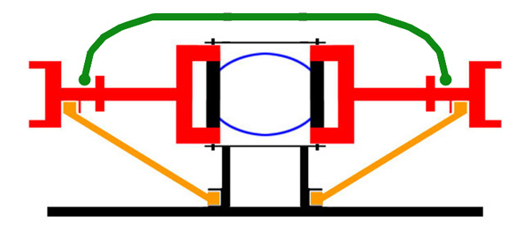
The dimensions from the left edge of the block represent the distance from center of the center section. The upper and lower control arms are set parallel to the center shaft and set 6 inches apart. The cumulative distance from left to right is 23.8125 inches for both the upper and lower control arm which set the camber exactly at zero degrees. The length of the center shaft is variable based on movement up and down.
I then moved the hub to a travel position 5inches up. The camber went negative a total of 0.9 degrees and the center shaft shortened up a total of .01 inches. Very nice ... I think Sammy was looking for a 1.0 degree negative change.
Now comes the surprise
When I moved the hub to a travel position 5 inches down the camber again went negative 0.9 degrees. In our stock Jag setup the camber goes positive when the travel position goes down andthis of course is bad for handling. I have checked and double checked all of the dimensions in the model and I can't find anything wrong. It appears that Sammy has captured the best of all worlds ... CV Joints on a Jag center section and incredible camber control.
Last edited by Joe (6/01/2011 8:10 am)
![]() Offline
Offline
So everything works smoothly huh? That's good news! The track should shorten up quite a bit too, starts @ 73", what's it at at full compression?
![]() Offline
Offline
Im gonna try something with that upper control arm. Ive always read and been told that you never put the control arms parallel like that and im going to try and lower the UCA inner mount and make some spindle changes.
What i saw so far with messing with that was the camber went all over the place, i guess its the difference with a suspension that gets 11" of usable travel vs a non adjustable vehicle. Seems like if i set it up the "right" way that its got nasty camber laid out which i cant stand.
![]() Offline
Offline
Using some simple trig tables ... at 5inches of travel the track width shortens up from 13.75 to 12.82 or 0.93 inches on each side.
![]() Offline
Offline
well i cant get the camber to act decent with the arms not parallel. I think there is just too much travel in this suspension compared to a non adjustable setup.
So im gonna check a few things from this against the bed and whatnot and if it looks good i can FINALLY get to the fun stuff!!
![]() Offline
Offline

Fascinating!!!! that solid works program seams like a fantastic tool. obviously for the forum you have to show still shots but I am assuming solid works will allow you to see the suspension going through it movement????

![]() Offline
Offline

Speaking of going through the motion! Motion for me began yesterday June 1st 2011. I dropped the car off the stands, measured vital dimensions and recorded. Back up on the rear stands and dismantling will begin today.
Going to try and mimic the Mustang1 design. Looks like I will have a wide variety of coilovers to choose from.
![]() Offline
Offline
Daze ... you are absolutely correct, I can move the parts up and down and see the results real time. It also has a variety of motors that can move the parts continuously.
![]() Offline
Offline
Any way you can save the animation as a GIF and send it to me?
![]() Offline
Offline

Ralphy wrote:
Speaking of going through the motion! Motion for me began yesterday June 1st 2011. I dropped the car off the stands, measured vital dimensions and recorded. Back up on the rear stands and dismantling will begin today.
Going to try and mimic the Mustang1 design. Looks like I will have a wide variety of coilovers to choose from.
I can't weight to see what you come up with. please take lots of pix and keep us posted.

![]() Offline
Offline
Sorry Daze ... not an option on this version
![]() Offline
Offline
Sammy ... I too am very interested to see how this all comes together!