|
|
|
 |
 |
 |
You are not logged in. Would you like to login?
![]() Offline
Offline
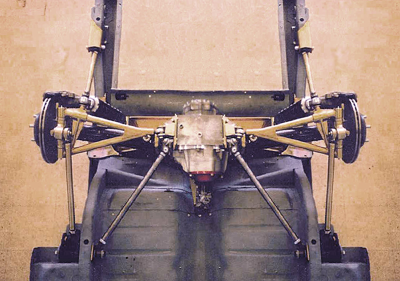
And so we begin ... I received all of the measurements. Below is an image of the model. I made some changes to help us work through the variables. In its current state I have not put in any of your measurements ... and the pivot points are purely random. The model has three basic components currently and as we start locking in dimensions I will create additional components. The block on the left represents the center section. It is locked down and does not move. The center shaft moves up and down without limits and we can measure that movement from center. Right now center is defined as centershaft angle = 0 degrees. The last component is the hub carrier (if you have better teminology for this part let me know) This is where we measure the camber positive and negative and again without limits. Obviously we have to subtract the angle from 90 to get the true camber. I have added pivot points for the upper control arm but in the beginning stages is not required. The model will move the components accurately without those points attached.
The one thing to keep in mind is that SolidWorks is extremely accurate so the better job we do of putting in dimensions the better job the software will do.
I need two things to proceed forward. First the pivot points on the CV. Does the CV Joint perform similiar to the half shafts on the Jag unit? By this I mean does it attach to the outer hub so that the length does not change? Also, as the center shaft moves up and down does it allow the hub to move independently again similiar to the half shafts. I really am clueless here.
The second thing I need is some guidance on the hub carrier. The center shaft mounts in the center of the hub and I assume that the hub will mount in the center of the hub carrier. I am also guessing that the hub carrier is something you are going to make. The pivot point for the lower control arm (LCA) on the hub carrier is currently in the same place as the stock jag hub. The pivot point for the upper control arm (UCA) is positioned randomly. All I really need here is your best guess on the lower pivot point.
Once I have these inputs from you I will be able to move the center shaft to a specific position ... like 11 inches up from 0 degrees. From there I will set the camber to some number that you want .... like 1.5, 2.0 3.0 ? negative. The software will then calculate the dimensions for both the LCA and the UCA. From there we lock in the dimensions and move the center shaft down to 11 inches the other direction and see what camber readings are generated. As we move the center shaft up and down the software can also alert us if there are conflicts, binding or other problems with our model.
I am working today so I won't be able to do anything further until Saturday morning. Enjoy!
![]() Offline
Offline
Center shaft has to plunge like CV's also( or like a slip joint on driveshaft with U-Joints) to compensate for different length upper and lower arms.
![]() Offline
Offline
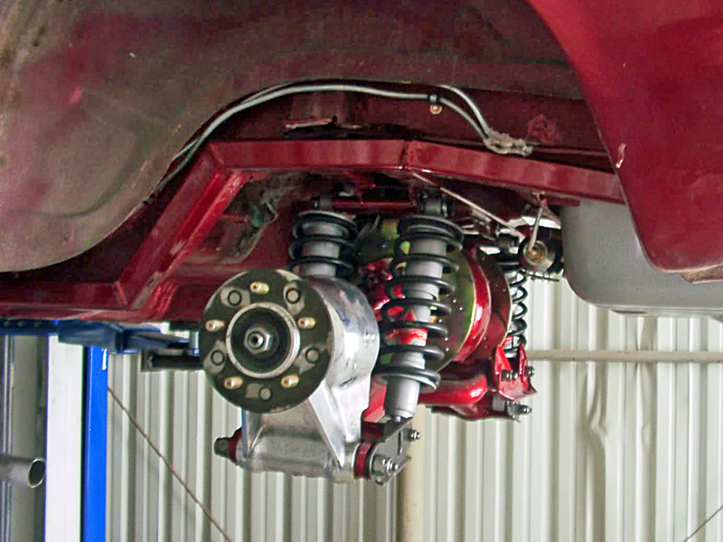
I was looking at the model and thinking about what Sammy had said in an earlier post that he was going to be using an upper control arm (UCA) to better control the camber changes. So I changed the model and started moving the control arms up and down to see what changes the camber experienced. I then recalled a photo of an IRS from TEAM321 that used an UCA. The pivot point on the UCA was quite a bid inboard from the outer hub so I started making chages to the model to see what affect this would have on camber. 
I started with UCA and LCA the same length 18" (this number is purely random just to give us some numbers). I then progressively moved the pivot point on the UCA only in increments of 1". This was done by removing 1" from the UCA and adding 1" to the hub so that camber remains at zero when the center shaft is at zero. Camber and center shaft length was recorded only at the extremes of travel +5" and -5" from zero.
LCA
/ UCA Travel Center Shaft Length Camber Change
18 / 18 5 / 5 13.65 / 13.65 -4.7 / +5.3
18 / 17 5 / 5 13.63 / 13.65 -4.9 / +5.3
18 / 16 5 / 5 13.60 / 13.65 -5.2 / +5.3
18 / 15 5 / 5 13.57 / 13.65 -5.8 / +5.3
So here are the results. As you can see changing the upper pivot point only affected camber when the center shaft is moving upwards from zero. I would have expected that any change would have affected camber throughout the entire range of movement.
Looking at the TEAM321 unit I noticed that the UCA is almost parallel with the center shaft. I am going to move the pivot point on the UCA at the center section end and see what kind of changes we get.
![]() Offline
Offline
That camber actually doesnt look bad and im gonna need some to clear the bed on this truck. I sent you some more measurements and updated info joe! I sent it to the email listed on your profile as i cant remember which one you gave me before.
Oh and i was looking at the control arms being 12" apart at the uprights. Need room for the axles and air bags, dunno what number you are running there right now.
Last edited by Slammy (5/13/2011 8:00 pm)
![]() Offline
Offline
anything new joe?
 1 of 1