
 |
 |
 |
 |
 |
You are not logged in. Would you like to login?
 1 of 1
![]() Offline
Offline

on August 3, 2010, 2:40 am, tyrellracing wrote:
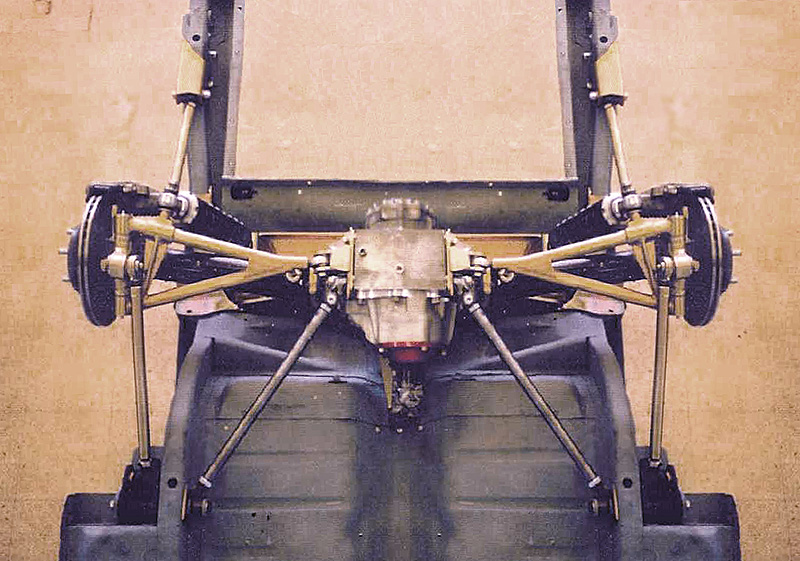
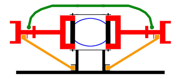
Have any of you thought of the issue that the Jag irs is a negative camber gain type suspension and when properly installed the half shafts should be parallel to the road surface? Adjusting the ride height by the springs alone with out compensating for the geometry issues will do strange things to the way the vehicle handles.You could possibly wind up with a positive camber gain if you place the diff too low then shim the half shafts to align you will make a very loose condition. ie.over steer city. If any of you have CAD software I recommend plotting the points and see what the differences in differential height and shimming to compensate does to the geometry.

![]() Offline
Offline

on August 3, 2010, 9:09 am, Daze wrote:
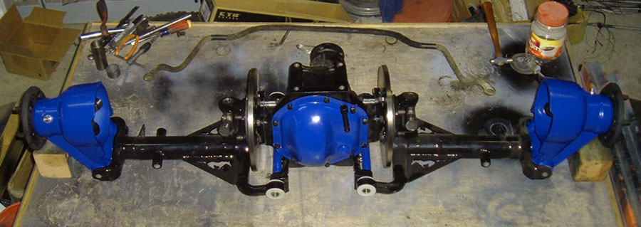
Thats an interesting point. I know you are not supposed to set camber...with the weight of the car on the wheels. According to my Jaguar shop manual the LCA needs to be firmly secured in a position parallel to the top of the cage before any camber adjustments are made. I see what you are saying and that if the rear end is not positioned correctly than the natural change of the camber curve would give you way to much or not enough camber at normal ride height. I took all this in to account when I first started planning. I built everything based on the measurements I first took of the location of the live axle. I wanted a similar ride height and have positioned my differential accordingly.

![]() Offline
Offline

on August 6, 2010, 7:13 pm, tyrellracing wrote:
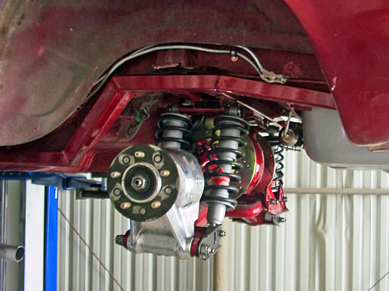
Very good! I am glad to hear you are thinking this through before you throw it in and try to drive it. I have a note book I started 25 years ago when I use to race my car in vintage production stock class. All of my set ups for different tracks and every possible dimension have come in handy over the years. I purchased the car when I was 18, I am 47 now. When I set up my suspension I started with sorting out the geometry at the ride height with out springs so I could put the suspension through its full travel and carefully check for problems. By doing this I could graph the change in toe as well as change in camber through the full travel. All of this info has been added to the note book for future reference. Then I tried to spring it firm enough to maintain that height. For me, getting a firm set up at the height I wanted with out cutting holes in my floor to get the shocks vertical enough to work with the Jaguar springs was the hard part. I do believe I mentioned that my first cross member got swiss cheesed in the attempt to find a suitable angle. I wound up using after market coils on the jag shocks. The valving on the stock type Jag shocks leaves a lot to be desired. My problem now is I am trying to find a type of rebuild able race coil over shock that is the same size so I can set the valving my self and not have to compromise. Avco sells a one similar but its extended length is one inch too long so I am trying to determine weather or not this will cause a problem if I catch air. That would be a bad time to break a half shaft u-joint!

![]() Offline
Offline

on August 6, 2010, Daze wrote:
I too have a book, but mine is more of a collection of info
I have hundreds of pages of other IRS installs on all kinds of makes and models as well as my own designs, drawings and calculations. I have spent more time building this project in my head than I have actually spent working on the car. I formulate a plan, build the parts, and install them all in my head before I ever make anything. then as I am building parts I do the same process over and over. The advantage is I end up with a well thought out project, and I rarely have to redo stuff as I worked out the bugs in the planning stage. The down side is that some times I over think things but that is half the fun.
Being that my car is not a track car, I am actually glad that the Jag unit was designed for both performance and ride quality. I am hoping to run the original springs with the stiffer KYB shocks and then set the upper mount so that the wishbones are parallel to the road or slightly down.

![]() Offline
Offline

on August 6, 2010, 2:08 pm, Joe wrote:
Camber Change When I saw the post from Tyrell about plotting the camber changes I thought what a great idea. Below are three different scenarios using the stock Jag dimensions ... 16" from eye to eye on the half shaft and 20.5" on the wishbone. Scenario #1 sets the half shaft at 0 degrees and camber at 0 degrees. Scenario #2 sets the half shaft at 2 degrees down and camber at 0 degrees. Scenario #3 set the half shaft at 2 degrees up and camber at 0 degrees.
The first point of interest is that as the half shaft moves up from 0 degrees the amount of camber change (negative)is greater than when the half shaft moves down (positive camber change) from 0 degrees.
The second point of interest is that when the half shaft is positioned at 2 degrees up or down and the camber is adjusted to 0 degrees the rate of camber change remains effectively the same as when the half shaft was at 0 degrees. After thinking about this for a while I think it makes sense. The hinge points of the half shaft and the wishbone are fixed on the center section (and the center section doesn't move) which means that the arcs that they scribe are always the same.
The last point of interest is one that I hadn't expected. As I plotted the points of camber change and saw the distance that the wishbone moved I started thinking about the shocks. The shocks of my IRS are KYB's and have a total movement of 4 inches. One of the articles I read stated that the Jag engineers designed the shocks to operate 60/40 compression/extension which means 2.4" down and 1.6" up which is based on the stock shock angle in the cage. Now change that shock angle and you change the effective rate of the shock and spring. Imagine that the shock was at 90 degrees to the wishbone ... the compression/extension percentage might be 80/20 or worse. And of course if you went the other way with the shock angle it changes the percentages to less compression and more extension.
All of this of course is subject to your specific configuration, vehicle weight, shock & spring package, etc. etc. But like everything I have learned from this forum ... the more input we get from a variety of sources the better chance we have of making our own best choices.

![]() Offline
Offline

on August 6, 2010, 2:20 pm, Joe wrote:
As I read through my post I realized that one of my statements was incorrect. When I moved the the half shaft from 0 to 2 degrees up and down I changed the arc of the half shaft by shimming the half shaft in/out. This did in fact change the arc that is scribed by the half shaft. The amount of shim was .025 in each direction and when compared to the length of 16" of the half shaft the impact is very small.

![]() Offline
Offline

on August 6, 2010, 7:32 pm, tyrellracing wrote:
Damn good! No dummies here! I am pleased that you had no problem sorting out the issues I presented. This is not to say that any of you would set up your suspension wrong, I feel that knowing where the pit falls are and how to avoid them is golden. I am sure that most of you probably are well on your way to completion of your installations and more than likely have your geometry correct. But I am as impatient as the next guy and sometimes want the happy results with out spending the time and effort to take a closer look. For those of you who are sometimes like me. That thread should provide in site to what can go wrong.

![]() Offline
Offline

on August 6, 2010, 10:19 pm, Daze wrote:
That chart and those observations are Fantastic!!!!!!
As to your first point I am not surprised that the system was designed with a negative camber curve. In most cases suspension travel will be up from ride height and the added negative camber will insure better road to rubber contact.
Your second point was on point
I had not heard of your third point but it makes sense. I would think that the ratio has far more to do with spring rate in relation to the weight of the car than angle. ( I realize the angle is a key part of efective spring rate) What I am saying is if you calculated the effective spring rate of of two new stock Jaguar coil springs set up as Jaguar intended and came up with a number (I will make one up) 150# rating of the springs in tandom and then then you went with two 75# springs mounted 90º to the road you should maintain that same 60/40 ratio. However given that the back half of a Mustang weighs less than a Jag, even at the original configuration the ratio should be changed.
One thing you do loos by reducing the angle of the shock but by maintaing spring rate is shock effectiveness. A shocks max effectiveness is when it able to travel at near max through full range of suspension travel. by mounting the coil overs 90º to the road you reduce shock travel, which in effect reduces its effectiveness.
Thats one place where the KYBs will be of benefit. As suspension speed increases the motion of the shocks should stiffen them. On my project I am hoping to slightly decrease the angle of the coil overs. this should stiffen up my springs and give me the ride height I want, with out moving to far away from the original design.
I don't have cad, so as favor to me could you plot the same camber curves with 2.125" removed from both the half shafts and wish bones?? I am curious how that will change the curve. I am thinking it will make it more aggressive, but would like to see the actual #s. Also if you have time I would love to see it with 4.3125" removed as that would be the curve for the original XKE unit.

![]() Offline
Offline

on August 7, 2010, 4:14 am, tyrellracing wrote:
I tried to measure the Jag spring rate using a jump scale I carry in my 5 ton truck but it was not accurate that low on its scale. The resolution starts at 500 lbs and using my hydraulic press I had the spring nearly coil bound before it registered any reading. I have access to a scale at work but I have no way place the scale in the 100 ton press to compress the spring in a controlled manor. The springs I am using on my car now were ones I purchased years ago for the King shocks on my sand rail. When the two of them were new, they were 21.5 inches long and roughly the same diameter as the Jag springs. They were not variable rate so the coils were equidistant and that allowed me to cut them in half making four springs 9.5 inches long after reforming and grinding the cut ends. When ever you shorten a coil spring by removing coils the rate increases so the original spring rate has little meaning.I am aware there are formulas for determining spring rate by wire diameter,coil count,length,and diameter but have not taken the time to find this info. I did not attempt measuring them because of the obvious reasons I described earlier. I now wish I had found a way to because they work great. The amount that you removed from the track of your suspension I believe will decrease the springs effectiveness but the change will be small. I have used KYB's gas adjust shocks on my cars for years and I think they build an excellent product but on my Shelby I like to have the option of disassembling my shocks so I can fine tune their dampening as well as rebuilding and re-charging them.

![]() Offline
Offline

on August 7, 2010, 10:04 am, Joe wrote:
My pleasure ... I had a thought that you might be asking for revised numbers. Also, when you get your's installed give me the actual angle on the half shaft and we'll run the numbers again

![]() Offline
Offline

on August 10, 2010, 10:03 pm, Daze wrote:
hey joe, I know you are busy, and I am by no means hurrying you along... but do you have an ETA on those camber #s???

![]() Offline
Offline

on August 13, 2010, 9:03 am, Joe wrote:
New Numbers for Daze As I was looking at the raw data it was difficult to really understand what was happening so I created a graph which I think tells a better story.
With the graph you can now see that the three lines are identical and are shifted up or down based on the starting angle of the half shaft. You can also see how the angle gets steeper (more camber change) as the the half shaft moves up (lower left corner) and how the angle gets shallower (less camber change) as the half shaft moves down (upper right corner). An interesting phenomenon that I would like to understand better.
The next set of data compares the stock jag IRS to the one that Daze shortened 2.125".
Probably the most interesting observation, for me anyway, is that as the half shaft moves down the positive camber change ends up being identical to the stock IRS. As the half shaft moves up and the camber goes negative the numbers come up short of the stock IRS, more like I would have expected. The only other observation is that the total travel up and down is less than the stock IRS within the confines of this data.
So here's the graph of the two data sets ... very boring

![]() Offline
Offline

on August 13, 2010, 8:38 pm, Daze wrote:
Thanks for the numbers!!!! I was surprised that shorter parts made for less change, I would have thought it would have been more. I got to thinking tonight, when you said 2º down or 2º up was that from out side in or inside out. In other words is 2º down where the hub side is below the center section side or is 2º down where the hub side is above the center section... all depends on how you look at it. I am assuming 2º down is the wishbone angling down from the center section , but I thought I better check. Can you do just one more?? would you be willing to plot the bones at 4º 6º or 8º down (hub side lower than the diff) and then lengthen the half shaft to set camber at 0º what does that do to the curve??? I know you are busy and I hate to ask, but I think it will shed more info on the over all camber curve of the suspension.

![]() Offline
Offline

on August 14, 2010, 10:51 am, Joe wrote:
I was also surprised. I think there is more to learn from this exercise. The 2 degree down translates to the half shaft pointing down from the center section. So the hubs would be sitting lower or the center section would be riding higher.
I will definitely run the additional angles.

![]() Offline
Offline

on August 14, 2010, 11:30 am, Ralphy wrote:
In what I have read on a Corvette board your halfshaft should never be pointing down. The numbers that really count are the loaded side of the car. When you point the halfshaft downward it will cause your halfshaft to elongate initially during load causing the loaded side to go more positive camber under small movements. The halfshaft should be horizontal to up. Not exactly sure how this plays with the Jag, just a mention!
I also believe the Corvette design gives more camber due to the geometry. Your two parts (halfshaft and dogbone) look closer and more parallel.
Ralphy

![]() Offline
Offline

on August 14, 2010, Ralphy wrote:
Seems measuring in degrees to compare camber is misleading. Daze shortened axle will have to travel a higher number of degrees for the same amount of suspension travel. Which plays right for a narrower track. Also at a static position say your zero axle height, shouldn't it equal -.5 degree? Thinking a rear irs should be set (aligned at -.5). Seems also they should intersect and cross? X

![]() Offline
Offline

on August 15, 2010, 6:07 am, Joe wrote:
One of the numbers in the raw data is total travel which was measured in inches. Your instincts are right on the mark, the amount of travel was less for Daze's IRS than for the stock IRS. As far as the set up, I do plan to run 1/2 degree of negative camber. The half shaft angle will be whatever it is because I will be using the stock Jag springs and shocks. For the purpose of comparison, however, I believe the numbers indicate (not conclusive yet) that changing the setup does not change the amount of camber change throughout the range.
Daze has asked me to run some additional numbers which should give us a better picture.

![]() Offline
Offline

on August 15, 2010, 11:49 am, Ralphy wrote:
I like to exaggerate in my mind to get a quick idea. In my mind if your halfshaft was only 3" long with 2" travel up and down your camber angle would be huge. Then if you made your halfshaft say 8' long you would have little to no camber change. This is all good of course because the narrower your track the more rapid you need camber change. I would also assume any shortening you guys are doing is coming off the hub end so your dampers do not move in.
Ralphy

![]() Offline
Offline
Well, ALMOST answered my question.
At the moment I am putting a STOCK XJ6 rear back into an XJ6 after rebuilding the brakes.
It's been apart a long time and I no longer know what axle/UCA shims were originally in place. ![]()
It will be a PITA to adjust camber after getting it back into the car, much easier to do on the bench.
To do that I just need to make a set of correct length temporary struts in place of the original shocks.
So what I am looking for is the factory 1984 XJ6 half-shaft angle at ride height.
This seems like it should be simple to look up, but is not.
Every try has got me lots of ads to buy a new Jag, or advice on models that are too new.
What I need is either the original angle at rested ride height or an eye to eye length for the strut.
Seems I saw this stated somewhere on this? forum in the past but unable to find it now. ![]()
![]() Offline
Offline

Thats an easy answer and I can help. The wishbone should be parallel with the road and in line with each other at ride height. I think thats what you were asking for? If not let me know.

 1 of 1