
 |
 |
 |
 |
 |
You are not logged in. Would you like to login?
![]() Offline
Offline
Bought the Speed-Wiz software since it was cheap enough and does much more than just suspension.
Found that it has Jag in the suspension menu so that should help with the El Camino.
Still pretty much stuck on the Spitfire/Merkur custom setup until I can figure out my basic starting points.
I know the track, wheel/tire sizes, and some basic differential dimensions.
Beyond that it's a blank piece of paper!
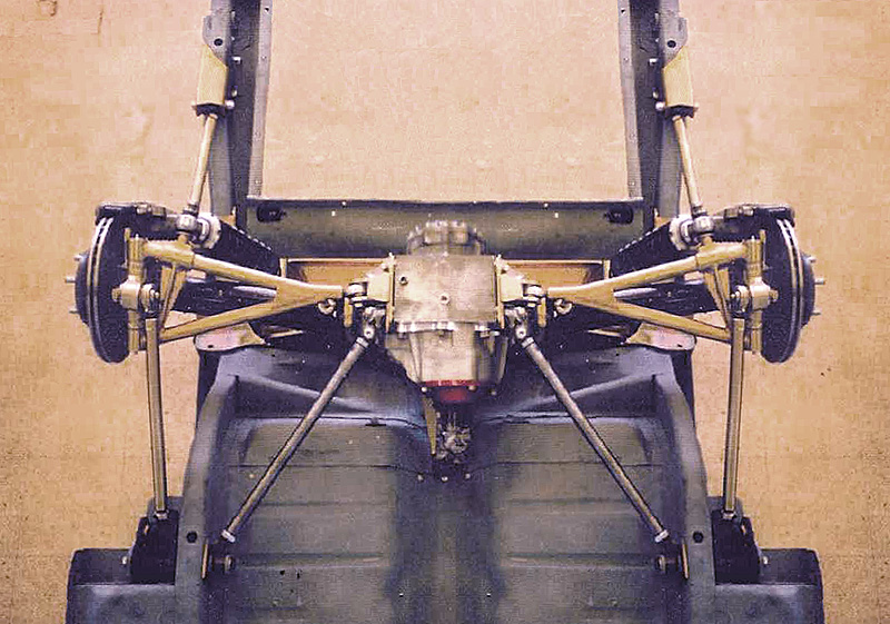
I have pics of a great design but no dimensions as the guy who was doing them insisted on his doing the installation.
Not practical with him being in England, beside which it seems he dropped out of doing them.
So it looks like I have to use the pics to try to get rough dimensions and come up with my own version.
![]() Offline
Offline
Gave up on doing what some one else had done and actually made some progress today.
Mostly cutting metal but I think I've figured out how to mount the Sierra/Merkur diff!
Good thing since it was keeping me awake.
Pics once I'm a little further along.
Basically I cut away most of the original Sierr/xr4ti diff cradle except for the mounting plates and a small section of the curved tube between them.
I plan to weld some rectangular box section steel virtically to the ends terminating at horizontal brackets that will fit the original Triumph mounts.
This is similar to how Toyota and such are usually done.
In addition I also cut away the center of the rear body mount.
I will now be able to add a horizontal bar to reinforce it while also fitting an original Sierra rear diff mount.
Hoping I can get one in Poly as the original rubber is too soft for my preference.
Once done the diff will be able to drop out the bottom easily as original.
I am off-setting it a bit in order to have equal length driveshafts.
With the diff in I will be able to work on the A arms, uprights, and shock mounts.
Since this is not a sancioned racer there are no set rules and I am free to do whatever I like for suspension.
Anyone have an "Ideal" rear suspension geometry for a 49" track?
![]() Offline
Offline
Some small progress.
El Camino frame is finally INSIDE on a nearly level floor!
Got the wheels bolted on and a stand made for the center section to keep it level.
With shims I will be able to adjust the components heights.
Bought my bushings so getting closer to fabricating the mounts.
Also bought some cast aluminum uprights for the Trick-6 rear.
Originally for a South African Lotus Seven replica, I got them from Canada.
They use my Merkur/Sierra hubs and axles.
Not beautiful but functional and I think I can clean them up using my milling machine.
Might even be able to lighten them a little.
![]() Offline
Offline
Small and steady progress is better than no progress.
![]() Offline
Offline
Beware, I have found the El Camino axle centerline and have a soapstone in hand!
Marking up metal for my mount now.
My design is probably overkill but I am triangulating the mount like crazy using original trailing arm mounts with bushings.
Rod ends sound trick but Want to isolate road noise as much as possible.
Also adding a set of low mounted trailing arm supports from the bottom of the frame to a tie bar at the front bottom of the diff.
Hoping I can put a sway-bar behind the diff.
My entire mount is a drop-out design.
Leaning heavily toward a watts link but a little concerned that the pivoting links at the lower arm will have to be pretty short to retain even minimum ground clearance.
Intuition says fore and aft links must be parallel, correct?
Fortunate that the frame is just about a perfect width.
Other than ground clearance what disadvantages might I find with the Watts?
![]() Offline
Offline
Visited a local "Rat Rod" car show today, never saw so much BAD engineering in one place before.
Some of it was truly incredible, but not in a good way.
To get the images out of my head I had to work on my El Camino/JAG IRS tonight.
Liking the Watts Link but not happy with the lack of ground clearance if I do it the easy way, like this but I have 15" wheels.
This pic might be an inspiration. I do not have space to add to the top of my upright as he did as I only have 4.50" between the top of the upright and bottom of my frame.
Need to keep 4.00" of travel.
But if I can extend the top of the upright inward 3.00" I could put the Watts above the axles and use the old trailing arm mounts for sway bar link mounts.
So how well do the Jag upright castings weld?
Thinking I may be able to cut pieces from my spare set and weld them together to get the additional width I need.
Would also weld the pivot point support at right angles crossing the top of the weld joint for a bit of reinforcement.
Hope this is clear as I've yet to master cad for illustration.
If doable this could make a clean Watts setup.
Need to stick my spare fuel tank in the frame to verify that I have plenty of clearance for the IRS, I think I do but should verify before going further.
![]() Offline
Offline
Do a search on this site for Boeing
I don't remember which member had his brother take an engineering look at the rear and came up with a design modification for the lower control arm. I incorporated this info and mod into my rear.
If your goal is to prevent wheel hop, I think this info will take you pretty far and much easier the the Watts setup. At least in my opinion.
Here is a link to another site with pics from my build:
![]() Offline
Offline
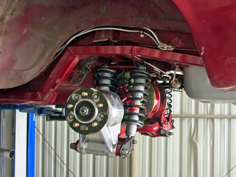
I have to correct my prior post. I can't find the post I was trying to reference. In short, the analysis came down to the coil overs creating a torque couple which alternate their compress and release cycling. This exaggerates the twisting of the lower control arm. The lca design lends itself to twisting by accommodating the in board brakes, coming in and narrowing down to the tube and then widening again for the hub.
The way identified to prevent the twisting is to run connecting tubes which reinforce the lca and prevent the twisting. This is what I did.
If anyone can find the original post, please post a link as I can't seem to find it.
![]() Offline
Offline
Not so concerned with wheel hop as deflection under acceleration and hard braking.
I've looked at 303 Radar's pics and found my '68 frame to be very different than the '59.
I have most of my conversion figured out and will actually cut some metal today. ![]()
If I can put the Watts Link at the top of the upright I will be about set.
Looking into forming a steel extension to do that.
Looked at what the Cobra guys are using but it is too similar to the one above that extends upward several inches.
I do not need to be taller, just wider toward the inside.
I need to re-read the information on using the later F40 carriers.
Seems they may be better suited for extending inward?
Not sure of their top of the casting height vs the XJ6 version.
There was something posted about having to shim bearings, and possibly needing an adapter U-joint?
![]() Offline
Offline
Finally got to pick up the rest of tube I needed and some threaded ends.
Metal supply house did not have some of the tube I needed but Summit Racing carries it.
May actually begin welding this weekend.
Also get to experiment with tube bending.
May try the fill with sand first trick to avoid flattening.
![]() Offline
Offline
Made some actual progress!
Ideal had to yield to practical in a couple of respects.
Lowered rear ride height l.00" to only 8" to the frame bottom just ahead of the kick-up.
GOOD.
Lowers center of gravity for better handling.
Helps to get my engine to sit normally for it's designed angle.
Brings the lower trailing arms for bracing the bottom of the diff into an almost strait line.
Brought my main diff mount up on the frame rails.
BAD.
Increases the bend I need for the upper forward reaching diff mount reinforcements.
Reduced compression travel to only 3", maybe 3.5"
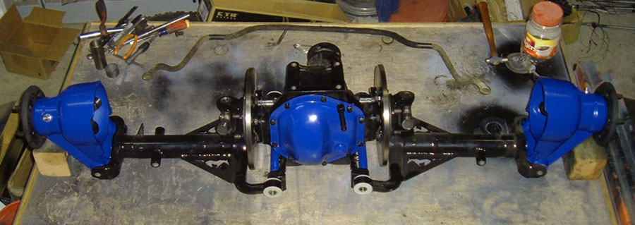
Here is an actual mock-up of my recent progress.
Main mount will be bushed at the ends.
Shock mounts and their spreaders are tacked in place.
Mounting points for the forward facing upper reinforcement are tacked in.
Lots of clearance for brake components.
Plan is adjustable shocks on the front and air shocks to lever the ride when I have a load at the back.
The round tube behind the diff is a mock-up for possible reinforcement of the rear lower diff.
30* black bars are my fixed points for shock simulation at ride height.
I have to bend tube for the forward reinforcement.
Despite my desire for light weight I seem to be overbuilding this.
I hope the added weight at least helps to balance me out front to rear.
![]() Offline
Offline
OK, somebody answer this simple question definitively!
Every other post on the subject that I see contradicts another!
Jag IRS lower arm level at ride height, or axle level at ride height?
It cannot be both!
I can see that with the lower arm level as I have it now, the axles will be slightly inclined upward going from the diff to the hubs.
Simulate 3" of compression and the wheel camber becomes noticeably positive.
This has to be settled ASAP, I'm close to welding in the main mount brackets.
![]() Offline
Offline
One more point to be clarified. (Yah, sure, just one more!)
Browsing the links posted into varied topics here I found a mention that a Watts lint to the top of the hub serves to eliminate wheel hop, and that a Watts link to the bottom of the hub acts as a trailing arm.
Is this correct?
Doing both might be possible but seems overly complex and likely to create a binding situation.
I really want to use a Watts link but am dismayed at the limited ground clearance I will have if I mount it to the lower arm near the hub.
Some jurisdictions will ticket you for anything that sits lower than the bottom of your wheel rim.
I find other issues with a trailing arm setup weather it is forward or rear mounted.
Getting to the point I have to decide what I am doing about this.
![]() Offline
Offline
Found my answer on the arms/axle angle question!
Whatever gives me -3/4* + or - 1/4* at normal ride height.
Strait out of my old XKE manual.
Now I need a better way to measure my camber.
![]() Offline
Offline
Good thing dismantling is the easy part!
Pulled my spare IRS to pieces today.
LCA mounts to the diff appear to measure at about 11* pinion angle so I must not be measuring them correctly.
The good news is that they are only drilled once, so all I have to do is reverse them and drill as I like for the correct pinion angle.
The 3:31 diff appears to be in good shape, just wish it was a power-lock.
Someone had been at this rear before, what we used to call a "Hammer mechanic".
So I have to replace my inside pivot pins.
Do shop around, I found the same part at prices ranging from $18.00 to $55.00 each.
At $55.00 each I would have made them on my lathe, at $18.00 I will probably just buy them.
Also have to buy bearings and seals for the rebuild.
Prices on those are pretty consistent and it's worth noting that EACH SIDE takes four needle bearing sets, so the total for both sides is EIGHT, not four as might be assumed.
Prices for these parts appear pretty consistent across vendors.
Going for the best U-joints I can find, whichever those may be.
Metal bits are going to be boring old black, might end up silver but I tend to think of the suspension as not being a visible part and I've never seen anyone keep a chrome one polished up properly for very long.
Still debating LCA reinforcement, I'm not going drag racing and it does look like I will have a low mount Watts Link.
Main question now becomes do I rebuild the 350 I have (Fairly cheap, more torque but lower RPM) or finish the hot screamer 327 build for fewer shifts on the twisty roads but less practical for long trips?
I really need an overdrive trans.
![]() Offline
Offline
Have you thought about using a trailing arm instead of a watts link? Much easier and might be cheaper with heim joints. Just make sure it pivots on the same axis as the lca. That's what I did and probably should have pointed out better.
![]() Offline
Offline
I did but do not like what I see as far as remaining a strong mount and clearing the drive-shaft.
I'm in Nevada, some of our roads are a bit rough and some shopping centers should have the manager beaten senseless for putting in such high speed bumps.
So ground clearance is a fairly major issue for me.
With the Watts the lowest point will be at the center of the tire diameter.
Trailing arms have to mount further forward and reach rearward from near the center.
I think the trailing arms would actually end up with more ground clearance issue than the Watts.
Trailing arms also appear to be a likely issue with my exhaust.
Next up is my frustration to date with trying to determine what shocks to buy.
Seems all the listings are for off-road buggies, 29" at ride height, 20" compressed, 40" extended!
Not even close to my need and it seems everything else is listed by make and model.
Not too helpful for CUSTOM car builds!
Koni prices so far have been insane, QA1 has no sizing information, may have to look at SPAX or GAZ?
![]() Offline
Offline
Regarding shocks, call QA1 directly or send an email. They called me back and spent 30 minutes talking with me, even though they didn't make a sale. I did go through Summit for their shocks in the end.
Trailing arms can mount to the front or rear, whichever direction you have the most clearance. The important part is the pivot axis must be inline with the axis of the LCA. Length is of almost no consequence.
Good luck!