
|
|
|
 |
 |
 |
You are not logged in. Would you like to login?
![]() Offline
Offline
Hi All,
I’ve been lurking for a while, and have picked-up some great info from Daze’s detailed explanation on how he fitted the Jag into his Mustang. I’m currently fitting a narrowed Jag rear end into a ’59 Hillman, and I thought I’d share some things that I picked-up along the way. I think you have to have 3 posts before you can post pictures, so those will have to wait.
This project was to be completely DIY so with the tools available I had to improvise on a couple of things to get it all done. For those that are contemplating taking on a fabrication project and doing 99% of it yourself, there are 2 items you will have to have – a lathe, and a mig of tig welder. You need a lathe to form both the “sleeves� for the LCA, and to reduce the diameter of the half-shafts, and a welder to make a sturdy jig for the LCAs and to plug weld them so that they stay in alignment. The only part of the job that is beyond my ability, and I would assume it applies to most of us is the final welding of the half-shafts and LCAs. That was the only portion of the project I farmed out.
I pretty much followed the instructions Daze has laid out, but since I only have a 7 x 10 mini lathe, I had to cut the original half-shaft in two, and machine each end separately because of the lathe’s length limitations. The new shafts are made from ¼� wall 1.75� dom tubing, and the amount you need to remove from the half-shaft ends is fairly minimal for a press fit into the tubing. For the LCA “sleeves,� I started with 2.25� solid steel and machined them to a snug fit (no slop, but not a press fit either). I chose the solid sleeves because they would allow maximum penetration, and the weight savings over hollow tubing is minimal when you are dealing with a 4� piece. I was lucky to find a welding shop that does oil field maintenance, so their specialty is certified pipe welding. They ground the gap I already had on the LCAs even wider and grooved into the sleeve about a ¼� . When I picked them up, you can look through the end of the LCA and see that the entire sleeve had turned cobalt blue from the penetration. The guy that owns the shop told me that anything can break, but this stuff won’t be breaking at the welds! I asked him about adding gussets, and he said if you want it for the “look� than go ahead and add it, but if you are looking for strength it just not needed – the LCAs are stronger now than they were before they were cut.
I built a jig to make my own half-shafts out of necessity. The local driveline shops would make up new shafts with all new components (to the tune of $400.00 each!), but they wouldn’t cut, or turn down any part of the original shafts for liability concerns. These are very easy to do, and if you have them professionally welded, I doubt you will have any issues.
A quick tip is that when you are disassembling your LCAs, leave the inner pivot needle bearings in place, along with the inner sleeves. It makes bolting the assembly into the jig a breeze, and trying to save 20 to 30 year old needle bearings is false economy as the online suppliers have them for about $8.50 each. Also, when removing the axle from the hub, some are more stubborn than others. I found that by making the tool that Daze made from angle instead of flat steel, it had more stability and didn’t bow under the pressure exerted by the press on even the most stubborn case. Another item I found is that it is absolutely necessary to file a groove in the LCA before you try to separate it with a pipe cutter as Daze suggests. IF you have a steady hand, you can use a dremel with a cutting wheel to make the groove easier and faster than with a file. I also found that by assembling the hub and flange with the bearings pressed in tight, you can use a depth micrometer to measure from the top of the splined flange to the top of the inner race and determine what size shim you need. Saves a tone of time assembling and disassembling to “guess� what size will give the exact preload setting.
I see there are some Tiger aficionados on the site. For those that don’t know, the ‘59 Hillman Husky is the platform from which the Tiger was built. While Tigers are an interesting piece of automotive history, and their owners are rabid defenders of the marque, the truth is that they have some severe drawbacks in the design of their front suspension and steering. I was lucky enough to obtain one of the very few coilover suspension units produced by Hokanson (toyzjunkie.com). He produced them for the Tiger, but anything that bolts into a Tiger, bolts right into a Husky. Having a fairly sophisticated front suspension is what led me to install a narrowed Jag unit rather than the more common 4-link most everyone else tends to favor. My project is kind of a cross between a traditional hot rod and a sports car. I went with a Snow White crossmember and front pinion mount kit. There are quite a few differing opinions on a bushed versus a solid mount, but remember that this is a street car. As someone once said somewhere on this site, if you have a squealing piece of metal being cut on a lathe, sometimes all it takes is a well-placed finger to stop it. It’s the same concept with a bushed mount – it doesn’t take much to reduce the harmonics being transmitted to the rest of the body structure, and since this car will never see any track duty, it is being built for street use and not a skid pad. The real objective of the bushed mount is noise reduction – not shock absorption.
One thing I rarely see being discussed is the cost of installing a unit, so I thought I would share my experience, along with the proviso “your mileage may vary.�
Cost of ’79 XJ6 Assembly 350.00
New Rotors 65.00
Rebuilt Calipers 140.00
Bearings, Seals 170.00
4 U-joints 100.00
Outer Pivot Bushings from Daze 86.00
Welding 100.00
Misc. Steel 60.00
4 Shocks 120.00
Crossmember 385.00
Pinion Support 155.00
Rear Tie Bar 35.00
Misc. Hardware, Shims, Paint 85.00
Total 1,851.00
The cost so far is relatively the same as an average 4-link; however, please keep in mind that the used unit that I picked up had been overhauled some time in its life, so nothing in the differential required replacement. If the unit you have requires work, or you want to install new gearing, or a posi, depending on what you have in mind it will add another 800.00 – 1,500.00 in additional cost. Additionally, I haven’t gotten to the point of fabricating the trailing arms which should eat up at least another 200.00 or more. So all in all this can and will become a very pricey undertaking. We all get sucked in by thinking we are getting some kind of deal on a 300.00 rear end, but just know that in the end you’ll be out 2,000.00 – 3,500.00, and even more if you have to farm everything out!
The specs on my rear are:
61.75� 1979 XJ6 Unit
3.31 to 1 – open diff.
Shortened to 51.5� overall (5.125� removed from each side)
4 Stock Jag Coilovers – After 30+ years of sitting under a 4,500 lb. vehicle, the spring sag worked in my favor perfectly for this installation.
If I make the “posting quota� I’ll put up some pictures.
Jim
![]() Offline
Offline
Wow! Welcome to the forum. Really good engineering. Looking forward to the pictures. You ended up a half inch shorter than an E-type. Should ride like a dream.
![]() Offline
Offline
Welcome aboard and thanks for sharing those innovative approaches. Get those 2 more postings and add some pics!
Cheers - Jim
![]() Offline
Offline
irstang wrote:
Wow! Welcome to the forum. Really good engineering. Looking forward to the pictures. You ended up a half inch shorter than an E-type. Should ride like a dream.
Could have saved a ton of shop time with E-Type LCAs and halfshafts, but the costs would go through the roof!
![]() Offline
Offline
Welcome aboard and thanks for sharing those innovative approaches. Get those 2 more postings and add some pics!
Cheers - Jim
Thanks for the welcome, Jim. Hopefully this will get me over the magic 3 post hurdle!
![]() Offline
Offline
A blank canvas...
Sleeves...
Ready for final welding...
Getting the halfshaft ends ready...


Back fro final welding...
Fabricated 10 ga. lower plate...
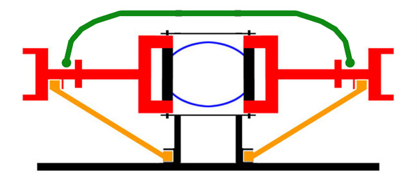
Hub press support...
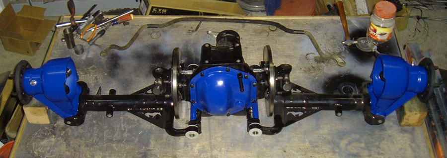
1 down, 1 to go....
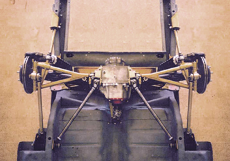
Finally mocked-up!!!
![]() Offline
Offline
Just a few more tid-bits...
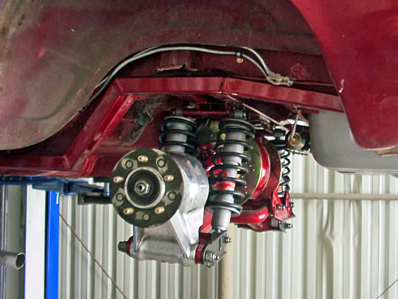
This is what's in the front-end:
For those that want to know, the pinion angle is @ zero, with the trans @ 2 degrees. Now that it's back on all 4 wheels, it all has to come apart for rotor and brake installation, final detailing, and so I can install the supports for the fuel cell and refinish the interior and underside with final paint before putting it all back together again.
Jim
Last edited by 59hillman (12/04/2014 9:25 am)
![]() Offline
Offline
Kudos on your build so far. It looks well planned and executed. I found the front suspension to be intriguing.
..Do you know what type spindles that front suspension kit uses? Have you decided on what size and how much back spacing the wheels you plan to use will have? Have you calculated how large scrub radius they produce? I too have a Tiger and am not impressed with its front suspension. The setup you are planning to use looks superior to the antiquated and poorly engineered Tiger set up. After all when the Alpine was altered to make room for a V8, they removed the steering box and its rear steer geometry so the mounting holes for the box and idler arm could be used for engine mounts. Then mounted a rack in front of the cross member to produce a front steer set up and needed room. When they did this, even with different steering arms bolted to the spindles they could not put the rack in the ideal location so, All stock Tiger's have miss located racks that produce bump steer. In my opinion that was a step backward from the original Alpine's geometry with nearly zero bump steer.
I have never seen a stock coil over suspension on a car like yours or a Tiger. By any chance do you have any photos of the old suspension?
Last edited by tyrellracing (5/27/2012 4:18 am)
![]() Offline
Offline
Kudos on your build so far. It looks well planned and executed. I found the front suspension to be intriguing.
..Do you know what type spindles that front suspension kit uses? Have you decided on what size and how much back spacing the wheels you plan to use will have? Have you calculated how large scrub radius they produce? I too have a Tiger and am not impressed with its front suspension. The setup you are planning to use looks superior to the antiquated and poorly engineered Tiger set up. After all when the Alpine was altered to make room for a V8, they removed the steering box and its rear steer geometry so the mounting holes for the box and idler arm could be used for engine mounts. Then mounted a rack in front of the cross member to produce a front steer set up and needed room. When they did this, even with different steering arms bolted to the spindles they could not put the rack in the ideal location so, All stock Tiger's have miss located racks that produce bump steer. In my opinion that was a step backward from the original Alpine's geometry with nearly zero bump steer.
I have never seen a stock coil over suspension on a car like yours or a Tiger. By any chance do you have any photos of the old suspension?
The front suspension unit is virtually all custom components with the exception of Mustang II spindles, rack, and brakes. I don’t have a picture of the old crossmember, but it is exactly what later ended up in the Alpine. I removed the steering box and idler arm and fitted repro Tiger mounts for the engine install. Each one of the Hokanson suspension units are custom made for a specific vehicle. They all vary slightly in track (stock, autocross, etc.), and because of where the rack sits; the distance from the crossmember mounting holes to the edge of front balancer sometimes differs too. None of them were kits – each one was delivered as a bolt-in unit. You can read all the history at toyzjunkie.com. I don’t think he produced more than 5 or 6 of them, so getting to see one in the flesh is rare. The Huskey is built like a tank, and I wanted to minimize weakening the structural integrity of the unibody. I chose not to tub the rear as the wheel wells are a major part of the body structure. The rear wheels are 15 x 6 with a 3.75 backspace. There is enough room to run a 205 tire in the stock well with the stock track of 51.5. If I wanted to spend a little more, I could get some custom rear wheels made in 15 x 7 with a 4.75 bs and run 225 tires, but the 15 x 6s will be fine on a street rod. The build objective is for a quick, quiet, and well-balanced street cruiser. If performance were the sole criteria, I would have back-halfed it and put in a 4-link.
![]() Offline
Offline
Thank you for your response. I kind of thought the spindles were Mustang II. There's nothing wrong with using them since they provide a reasonable King pin inclination and axle to ball joint relationship for an acceptable ride height. The entire front suspension on Tigers is attached to the cross member. This is one attribute I really like about the Tiger's design. The Suspension you posted really looks like a clean solution as far as the redesign of the cross member goes. I am surprised that they are unique to each order. Its rare for a company to be able build for each customers application. Thats pretty cool in any ones book.
I put a narrowed 9 inch in my Tiger years ago after the stock unit let go in a big way. I am still using the stock leaf spring suspension as well. I have a spare Jag XJ6 rear and after seeing how clean your install came out I am thinking about installing it in my tiger. I hope you dont mind having your design copied. It just looks too sanitary not to.
I put a Jag XJ6 irs in a 67 mustang some time back and kept it full width by using wheels with enough back spacing to maintain the track width I wanted. This produced wheel hop. I think one of the ways wheel hop can be eliminated is by narrowing the Jag unit. I have a Monarch 22x72 engine lathe and a Bridgeport so narrowing will be a piece of cake.
My intended goal is to gain control when cornering on the crappy roads around the Portland area not drag racing. Right now my Tiger is my daily driver so this plan will have to wait till winter.
Last edited by tyrellracing (5/27/2012 11:53 am)
![]() Offline
Offline
Thank you for your response. I kind of thought the spindles were Mustang II. There's nothing wrong with using them since they provide a reasonable King pin inclination and axle to ball joint relationship for an acceptable ride height. The entire front suspension on Tigers is attached to the cross member. This is one attribute I really like about the Tiger's design. The Suspension you posted really looks like a clean solution as far as the redesign of the cross member goes. I am surprised that they are unique to each order. Its rare for a company to be able build for each customers application. Thats pretty cool in any ones book.
I put a narrowed 9 inch in my Tiger years ago after the stock unit let go in a big way. I am still using the stock leaf spring suspension as well. I have a spare Jag XJ6 rear and after seeing how clean your install came out I am thinking about installing it in my tiger. I hope you dont mind having your design copied. It just looks too sanitary not to.
I put a Jag XJ6 irs in a 67 mustang some time back and kept it full width by using wheels with enough back spacing to maintain the track width I wanted. This produced wheel hop. I think one of the ways wheel hop can be eliminated is by narrowing the Jag unit. I have a Monarch 22x72 engine lathe and a Bridgeport so narrowing will be a piece of cake.
My intended goal is to gain control when cornering on the crappy roads around the Portland area not drag racing. Right now my Tiger is my daily driver so this plan will have to wait till winter.
The guy that built the front end is a master fabricator and not a company, so each unit was a custom build. His goal was to create a unit that solved all the Tiger issues, but could be bolted in without modifying the chassis. Most Tiger owners are bent on originality, so chopping up the front end to put in a Mustang II unit will usually never happen.
Feel free to copy the design; I’m sure I borrowed more than a few things from around the web on this install too! The side panels welded to the crossmember are fabricated from 10 ga. It doesn’t show the final installation in the picture, but it is bolted in with eight grade 8-7/16 bolts on each side. 2 surround the outer edge of the pinion support brackets, 1 is in the center of the bracket, 4 surround the crossmember, and 1 is between the crossmember and the pinion support bracket. My old welder buddy advised against welding on 50+-year-old frame rails and favored a bolt in. He said you’ll rip the frame rails out of the car before the crossmember ever comes loose. Looking at the final install, I think he hit it right on the head. On your car (with hindsight on my side), I would give some consideration to narrowing more in the range of 50 to 50.5 inches. I think you’ll have an easier choice with wheel and tire sizes.
![]() Offline
Offline
I agree with your idea of bolting the cross member in. Thats how I put the IRS in my mustang and it really made working on the assembly as a whole much easier. I dont want to tub the Tiger but I do want to use larger tires and wheels. The 50 inch figure sounds right since the 9 inch is 52 inches wide right now. The only obstruction to using wider tires are the frame rail and the outer fender lip I have no desire to alter them any more than to radius the inner fender lip further. In my opinion the real benefit would come from the dramatic reduction in unsprung weight. The old 9er is pretty heavy and its all unsprung
![]() Offline
Offline
Nice write up. Welcome to the forum
![]() Offline
Offline
Forum has been a little quite, so I figured I'd post some progress pics. It's slow going trying to jam 10 lbs. of engine in a 2lb. bag, but it's slowly getting there.


Last edited by 59hillman (12/04/2014 8:36 am)
![]() Offline
Offline
Looks nice.
 1 of 1