
 |
 |
 |
 |
 |
You are not logged in. Would you like to login?
![]() Offline
Offline
I have some questions on a z-bar design, or longitudal watts link.
Is there a thread here regarding the anti-squat or brake hop geometry of this type of suspension? Can you link me there or give me a search clue?
what is the official name of this type of of link system? Dirt modifieds seem to call it a Z-bar. I have also found it referd to as a longitudal watts link.
Think C4 corvette, but with the upper link facing towards the rear of the car and mounting to the chassis back there.
What are the pros and cons?
Thanks.
![]() Offline
Offline

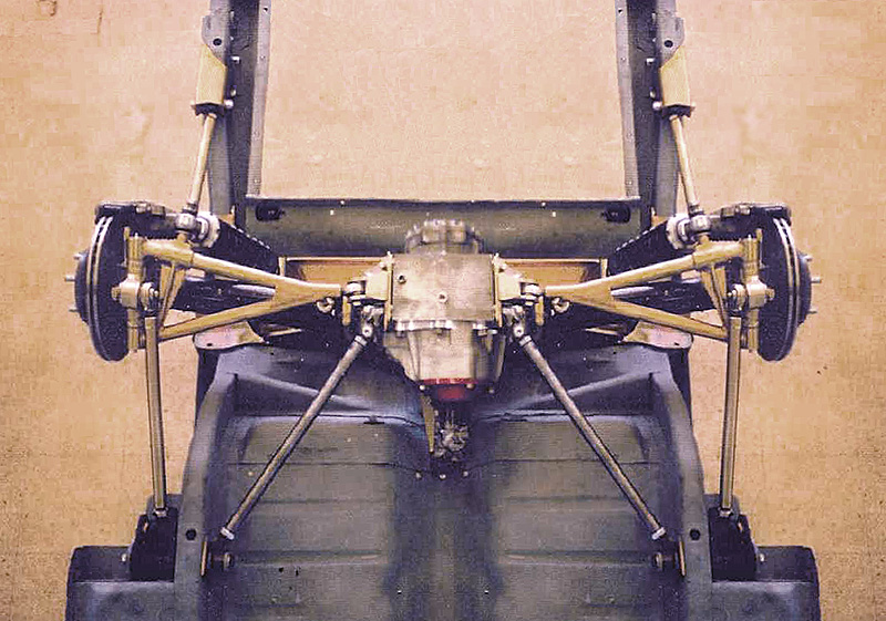
Oh boy! Have you noticed the upper right picture at top of the page? That's the mid sixties design Ford almost introduced on the Mustang. It was called the T5 design. The unique design mechanics is the upper rearward link inverts effects. It would take lots of words and explaining it's tributes.
Ralphy
![]() Offline
Offline
You're not refering to this are you?
video:
Ken
![]() Offline
Offline

I think he's refering to something like this. When you click the link, note the first pic is upside down go below it, it's flipped.
The manufacture is a member here, DUANE, Duane Carling. NBF as far as any atributes discussed here, very little has been. I brought it up once.
Oh, here!
Ralphy
Last edited by Ralphy (8/30/2013 8:20 am)
![]() Offline
Offline
 Yes, that's it! The inverted photo.
![]() Offline
Offline
I'm going to read up there in the linked thread. Thank you. Right now I'm waiting on some explorer IRS parts for R&D. I'm looking at this design as I do not really have any room for a forward upper link without major surgery.
![]() Offline
Offline
Sofar its looking like a single lower camber link with a toe link for me. Not because of that thread, but as that's what my proposed knuckle already has.
![]() Offline
Offline

When Klaus Arning built the original for Ford, they used Corvette parts. This design also allows for roll steer. The Y shaped camber link will progressivly increase the roll steer. The higher the front mount at the upright is. Klaus Arning was the original Ford designer for Ford. He also designed the rear suspension for Carol Shelby's 427 AC Cobra. As I said before Duane Carling a member on this board, will build and install a T5 design in your Mustang.
Duane's site.
Here's some real good reading from Duane's site.
Main page pdf's came from
Note this, little is mentioned about the mechanics of the fore and aft links.
Here's where I started, A poster at Club Cobra installs a solid axle with a Z Bar setup.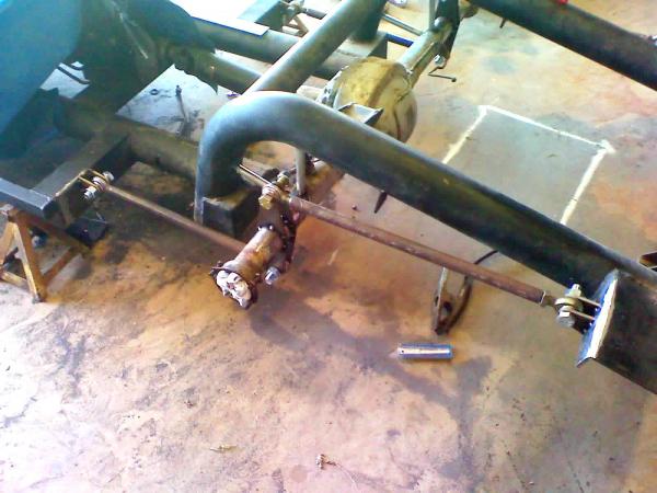
Ralphy
Last edited by Ralphy (8/31/2013 6:48 am)
![]() Offline
Offline

What knuckle/upright are you using?
Ralphy
![]() Offline
Offline
Sorry about the delay. I'm trying to use the cobra knuckle.
keep in mind the cross axis joints of the cobra knuckle have about 12 degree of out of position movement. This would give me about 5" of rear travel with the design I questioned above. This isn't enough for me I feel, and I'm looking into fitting a com12 spherical housing as a joint replacement.
im also not happy with the flange diameter of the cobra hub as my car is a GM.
ive obtained a single ford explorer hub and rear cv for fitment tests - hoping to combine them with the cobra knuckle, cv bar shaft, and inner 31spl cvs.
the explorer uses a much larger bearing, and the outter cv stub seems to have more splined area and less threaded area. Right now, for the life of me I can't seperate the explorer outter cv from the shaft to see if the inner spline dimensions are the same as the cobra. The hub/outter cv are not the same 28 vs 29.
so, that's where I'm at.
thanks.
![]() Offline
Offline
Also, is there a thread on how my cv shafts should be positioned in the car at ride height?
i understand that they shouldn't bind throughout the travel, but should they be straight or at a slight angle outters towards the rear or or ground?
i believe they will remain rzeppa outer, tripod inner.
thanks
![]() Offline
Offline

I'm trying to figure in my mind how or why your going from a Cobra design to the T5? Do you have clearance issues? Some of the biggest users of an IRS are AC Cobra kit car guys. The best and almost only board for them is Club Cobra. I'm sure someone there can help on the halfshafts.
Home Page
Forums Page
Become a member and use the search tool.
Ralphy
Last edited by Ralphy (9/06/2013 4:44 am)
![]() Offline
Offline
![]() Offline
Offline
 Space issues I do have. I can cut if need be. I'm just weighing my options. The car is 35 and the frame rails didnt rust - almost a shame to cut them.
![]() Offline
Offline

I'm sorry my bad these are all T Bird!
If you go to the Ford IRS picture thread. Post number 4, 12, 30, 33, show AC Cobras with Mustang Cobra IRS units. Or at least Cobra like.
As far as what's most often used in a AC Cobra. Back in earlier years, Jag was heavily used. Later some used C4's. Look at it as what was available at the time. Mustang IRS units were not easily found in a bone yard.
Ralphy
Last edited by Ralphy (9/07/2013 5:40 am)
![]() Offline
Offline

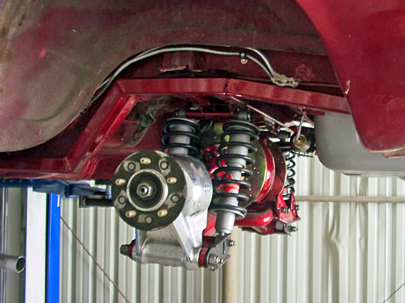
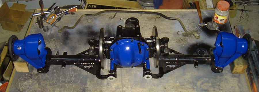
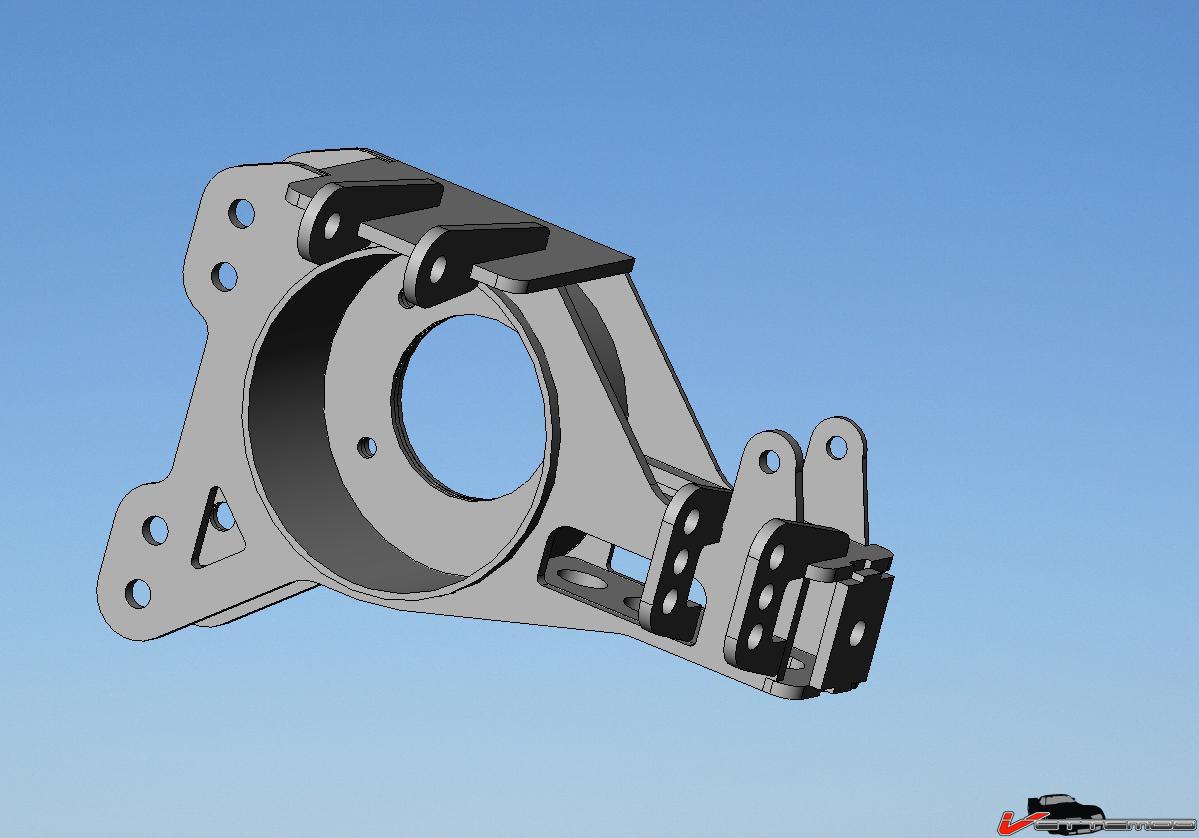
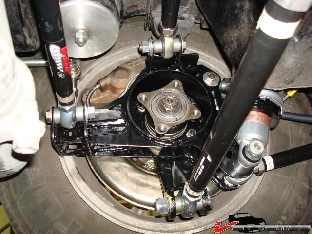
Okay, so your using a Cobra knuckle, Z Bar longitudinal fore and aft links.Then unlike a C4 you'll have an upper control link above your splined halfshafts, right? That's almost exactly what I was thinking about, but C4 style fixed length halfshaft minus the upper link. The issue I figured was an unusual toeing through suspension travel. Location and length of the toe link would be very critical. The issue being the knuckle/uprights movement. It will rotate a few degrees through travel and move fore and aft. I like the toe link behind the halfshaft since it's the most rigid point to reduce twisting of the knuckle/upright with the C4 halfshaft. My shade tree ideas are a toe link that can be adjusted/moved at it's inner point. A few guys are building a conversion for the C3 that is similar to the C4. The difference is the toe link is equal length to the halfshaft and it can be moved up and down at it's outer mounting point. As below, he also uses an upper link and a splined halfshaft.
In the middle pic, the two brackets with three holes are the adjustments for the toe link. Again these pics are from a C3 Corvette.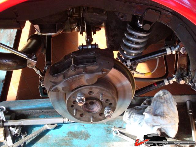
Last edited by Ralphy (9/07/2013 7:00 am)
![]() Offline
Offline

[url=]Circle Track Cars
On a Z-link four bar type of rear suspension, there is an indexing effect as the chassis travels that will tend to rotate the birdcage and, along with it, cause changes in the height of the bottom of the spring mount. In this example, as the chassis moves down, the arms straighten out and that causes the birdcage to rotate. When the spring is mounted behind the axle tube, the indexing stiffens the rate felt by the chassis on that side. You can mount the spring in front of or behind the axle for different effects. If the RR spring is mounted to the rear of the axle, then as the car goes into the turns, crossweight will be reduced because load will increase for the LF and RR tires. Mounting the spring in front of the axle will increase bite, or left rear weight.
[/url]
Rear Geometry
There are probably several hundred different configurations we can use in typical four-link or Z-link rear suspensions. If we combine the different bar angle possibilities with the various spring placements, indexing properties of the birdcages, pull bar angles and spring rates, lift arm rates that regulate lift on acceleration and compression during braking, shock rates for the four corners, plus the fifth and sixth coil, we begin to get the picture. The adjustment combinations are even much more than those for a Formula One or Indy car.
We need to decide what we want to achieve and then set the bars, etc., so that the car will do what we want. The various linkage designs from the four-bar to the Z-link offer possibilities for changing the rear steer characteristics as well as the distribution of weight while decelerating and while under acceleration loads.
Each side can be adjusted with respect to "front to rear movement" as the chassis moves vertically, or to steer either direction depending upon what the chassis is doing on a particular side of the car. The four-bar can be set up to move the wheel considerable distances fore and aft, and that movement can either help performance or put you out of contention.[Dirt Car Suspension Setup Guide]
Most Late Model cars utilize birdcage-type attachment points where the linkages connect to the rear axle tubes. This allows the rear end to be free to rotate.
[Dirt Car Suspension Setup Guide]
Most Late Model cars utilize birdcage-type attachment points where the linkages connect toRear geometry deals not only with wheel movement, but also the forces associated with acceleration and braking. As we accelerate, there is a great amount of torque applied to the rear axle housing, and dirt car manufacturers have designed several systems to take advantage of that force. Among the most popular systems are the pull bar and the lift arm. Both help cushion the torque related to instant application of power to help the rear tires maintain grip with the racing surface, and to control the forces of engine and wheel braking when decelerating.
Both systems can utilize a shock that will control the speed of movement both ways. This is essential, because a spring will react relatively slowly when being compressed, and violently when released from compression. The shock controls both, but obviously must do much more work in the rebound mode.
The two most common types of rear suspension links are the Z-link (left) and the four-bar (right). Some teams will use a Z-link on the right side of the car...
Read more:
Last edited by Ralphy (9/08/2013 5:33 pm)
![]() Offline
Offline
Thanks Ralphy.
its proving to be very difficult. My nam is Jon btw.
the explorer cvs are basically not usable without an extreme amount of effort. They are really, really non servicable in a way that would take destructive methods to remove the outter cv. Using four explorer cvs to assemble two may be an option, and modding the outter and inner cvs to run a porsche 930 or 934 would possibly be a better option. But right now I'm considering the explorer cv research project a small defeat- about $80
On the Z-bar, like I said before, the cobra cross-axis don't really have a comfortable amount of non-radial movement. There is the option to mill a new insert for a com12 with more angle. Which is looking like on of the two most plausible solutions.
I had considered deviating the forward and horizontal bearing into two seperate bearings, but this caused a series of issues that amounted to it being non-feasible. Some of these problems included the bearings be on the same axis for the suspension to be safe, and problems with keeping the arms not twisting due to the fact that springs, shocks, and sway bars must be mounted to them.
Second most plausible solution is to accept defeat on having tuning options in the forward instant center and run a trailing arm with two inboard links for camber and maintain the toe link. This would be somewhat of an odd design, and one clearly designed around my rear frame limitations. Kind of like a C3 corvette with two additional hinges in the trailing arm to adjust toe-in seperatly from the trailing arm.
This may
This maybe the sort of thing,
![]() Offline
Offline
This may be the sort of thing where any attempt to keep the stock rear rails is a mistake. Clearly I will have to add to them regardless of what I do.
i didn't mean to deviate my reply, but sometimes I have a hard time scrolling up and down during my reply. I'm using an iPad, and that may be the issue. Also I'm new to posting here, and its a learning curve.
thanks for your input. It looks as though I have a long way to go on this project, and the research process alone is quite the feat, before any fabrication can take place.