
 |
 |
 |
 |
 |
You are not logged in. Would you like to login?
![]() Offline
Offline
HI all- Im new to this forum and Im looking for some installation knowledge, I am unable to upload phots yet. Im hoping someone here can give me some advice. Here is what I have:
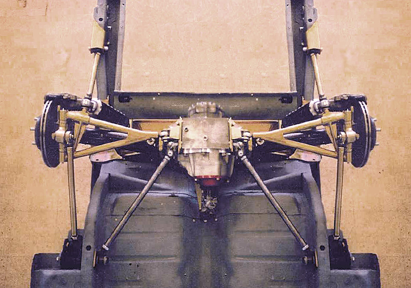
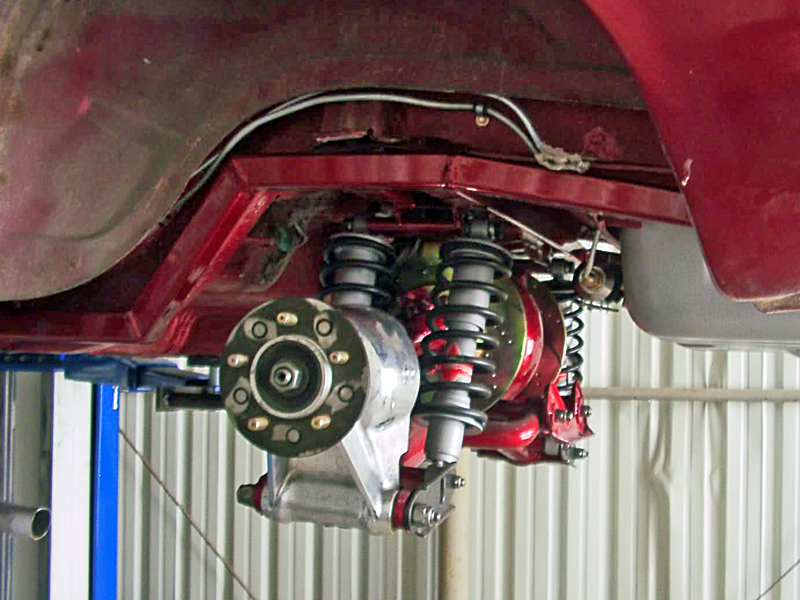
1951 Ford F1 Pickup. Jag XJR front end and what I was told early (70's S type) IRS. Inboard rotors etc.
So I have it all installed and its ready for Coil over shocks. I tried to mimic the travel of the LCA and I noticed the entire center is getting pushed around by the Radius arm. what did I do wrong in the build up? I can see that the radius arm would change in length as the axle moves up and down but I am puzzled as to how to acheive rigidity in the center section.
Last edited by fittyfod (3/25/2013 8:37 pm)
![]() Offline
Offline
I hate to suggest this, but post a couple of jokes or go poke some fun at this tire suggestion (really I think Pirelli is smoking somehing or it is early April's fool):
Then post a couple of pics. Right now, I'd have to say you don't have a solid cross member or the cross member isn't solid in place. Also, I would check the radius arms, because they don't seem to be inline with mounting point to the LCA on the center section. They need to be completely inline or they will bind. On the upside of bind, you'll find you weak link really fast when something wears out ![]()
Once you have some pics, we'll have a better idea. After all, one picture is worth a thousand speculations ![]()
Last edited by 303Radar (3/26/2013 9:29 am)
![]() Offline
Offline

![]() Offline
Offline

![]() Offline
Offline
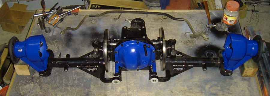
As you can see the Radius rods shoot inward from the LCA outermost mounting point and are angled up to connect to the forward mount. Is this right?
I bought this set up that was going into a mustang, I guess CWI put it all together. that company is gone now... So I used those rods and fabricated the forward mounting points. They point in towards the drive line.
Last edited by fittyfod (3/26/2013 8:34 am)
![]() Offline
Offline

![]() Offline
Offline
If all your bolts are tight, I don't see how anything can move ![]()
I don't think the radius arms should be pointing upward. I'll let Daze comment as I think he has a similar setup. You might be seeing the result of some bind in your setup. To test this out, take some metal straps, mount one end where the rods meet now, drop your rods down to the same level where your LCAs meet the center and connect them to the straps. If moving the LCAs doesn't rock the center, you found the problem, you need to lower the mounting point of the rods.
The easiest way to find where to mount the front of the rods is to run anything which is long (five footi'sh) and similar diameter to the long bolt which connects the LCA to the center. Run your tube through the center and LCA, so it holds them like a bolt. The line which is formed identies anywhere you can place the mount for the radius rod. If this isn't clear, maybe PhantomJack, TyrellRacing or Daze can explain it better. This is my first attempt at describing how to find a good mounting point.
![]() Offline
Offline
I think I know the problem, when you stated "I can see that the radius arm would change in length", I think you identified the problem without knowing it. The radius arm is not mounted in the correct place and is binding pretty badly. Try the steps in my above post to identify a better mounting spot. I had a similar problem in trying to use an existing mounting point.
![]() Offline
Offline
Ill give that a try this weekend, dodging the Eaterbunny!
![]() Offline
Offline

fittyfod,
Draw an imaginary line thru your LCA's inner mounting points. That is where your radius rods/trailing links should be mounted. The same axis as the LCA. Being above I would guess tries to push your wheels back or toes them out when jounced. Rebound would toe in. Toeing out like this causes over-steer. The same issue the C3 Corvette design was built with. The worst direction, being that neutral or toe in would be better. Neutral the best IMO!
Ralphy
Last edited by Ralphy (3/26/2013 12:19 pm)
![]() Offline
Offline
I see the whole center section move. It is binding on the radius rod. Ill drop the rod forward mounting point down to see if this will solve it.
Another question is that these radius arms are angled inward. Could they be mounted straight forward on solid heim joints rather than these rubberized bushes? I dont think I could get those replaced. Dont look like they come out. I can fab up some straight DOM tubing with threaded bungs in the ends and attach heims.
![]() Offline
Offline
I'm going to echo everyone else, The "angled up" is what is getting you. It is going to move some but thats what the bushings are for. all you can do is minimize it.
![]() Offline
Offline

Moving it outward solves nothing. Look at it this way, if you used a long stud/bolt thru the LCA's inner mounting points. Then continue all way forward to the front mounting point of the trailing link. You will have zero bind/motion. All points wil move in concert. Heims are great but don't, so if your off as you are now it will only complicate things. First find the right point and then add Heims. Heims will transfer vibration/noise more. But performance wise much better. Don't buy cheap Heims! Your on the right track. Go to the link on my posts COMPONENTS for your Build, Phantomjock started, there is a manufacture listed. Check out post #16 and #17.
Ralphy
Last edited by Ralphy (3/26/2013 3:48 pm)
![]() Offline
Offline
Here is a photo I made that help me visualize it. It creates a giant "A-Arm" of sorts.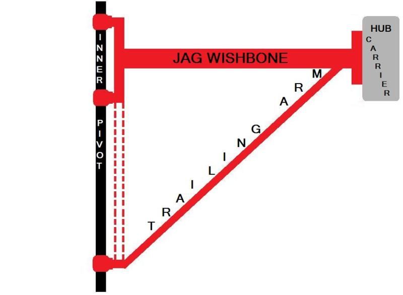
Last edited by IRON MAIDEN (3/29/2013 12:09 pm)
![]() Offline
Offline
Iron - Nice pic! I'm going to print it off and give it to my chassis guy to describe exactly what I want him to do.
![]() Offline
Offline

Sure like the brake hose setup. Especially the E brake kit. Where did you get that from?
![]() Offline
Offline

303Radar wrote:
Iron - Nice pic! I'm going to print it off and give it to my chassis guy to describe exactly what I want him to do.
Thanks. When I first started trying to research the Jag rear and how I was gonna do my setup, this was the one area I just couldn't visualize. I have build threads on the Hamb, Killbillet, RatRodsRule, and I post here as well. All 4 forums have great members who were able to answer my questions but I still couldn't wrap my head around this one. One night, I woke up to this thought. It just clicked. So the next morning I pulled up the program, microsoft paint, and made this diagram. For whatever reason.... this diagram clears it up for me and helps me visualize it. I've posted it on all 4 forums and I get the same feedback everytime. Pictures are worth a 1000 words! Glad I could contribute to the cause..
![]() Offline
Offline
Iron - I saw the same e-brake setup in a Speedway Motors catalog. In the catalog, they show it is for a Ford 9 inch. But it is the exact setup.
![]() Offline
Offline
The range which is established identies anywhere you can position the install for the distance rod. If this isn't obvious, maybe PhantomJack, TyrellRacing or Mindless reverie can describe it better. This is my first effort at explaining how to look for a increasing factor . . . . . . . . . . ..
"""Surfers Rent A Car
2/11 Northview Street Mermaid Waters Gold Coast QLD 4218
Phone: (07) 5572 0600"""
Cheap Car Hire Brisbane
Last edited by JimpetRICia (4/12/2013 11:43 pm)
![]() Offline
Offline
I would examine the distance hands, because they don't seem to be inline with increasing factor to the LCA on the middle area. They need to be absolutely inline or they will combine. On the benefit of combine, you'll discover you poor weblink really quick when something would wear out . . . . . . . . .
"""Surfers Rent A Car
2/11 Northview Street Mermaid Waters Gold Coast QLD 4218
Phone: (07) 5572 0600"""
Cheap Car Hire Brisbane
Last edited by JimpetRICia (4/12/2013 11:45 pm)