
|
|
|
 |
 |
 |
You are not logged in. Would you like to login?

![]() Offline
Offline
Bear with me here...
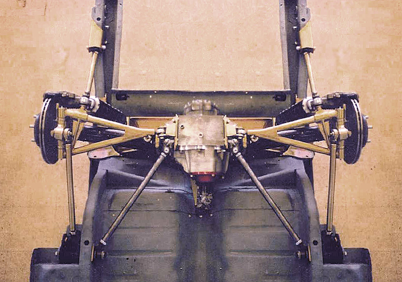
Here is a GM A-Body frame and rear suspension:
What if I were to use the factory lower trailing arm mounts to run an arm back to the upright, making a pseudo-lower control arm? You would need Johnny-Joints at both the diff and at the frame so they could pivot on two planes. Likewise, the lower arm would be a C-4 Corvette style with a johnny-Joint at the differential mount for the same reason.
Thoughts?
Bill
Last edited by ProTouring442 (10/15/2012 2:24 pm)
![]() Offline
Offline
Basically I am thinking of making a large lower A-Arm. One end would pivot at the original lower trailing arm location, while the other end would pivot at the diff, in the same place as a C-4 Vette, or Jag.
The upper arm would still be the halfshaft, and so you would still have a decent camber curve.
As the suspension is compressed, the wheel would toe in (I don't know how much), just like with a C-3 or C-4 Vette.
I wish I had something I could draw it out on, but...
So what do you guys think?
Bill
![]() Offline
Offline

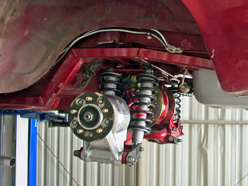
PT is this similar to what you mean? Minus the upper link to sit on instead of the HS?
C3 toes out, over steer, C4 toes in, under steer. This concept should, I think toe in. Roll Steer seems to be an idea of the past except as a preventative from losing it so easily when you stab the throttle. That was a C3 issue when cornering the rear wants to kick out. As best I've seen there should be app., .3 degrees total toe change. That's around 1/3 degree in case your not sure what I typed. LOL!
Phantomjock, have you ever looked at the caliper mount for a C3 closely? Can it be indexed 90 degrees forward over the front easily? That is if you had a modified upright more C4 like?
Ralphy
Last edited by Ralphy (10/15/2012 6:14 pm)
![]() Offline
Offline
Ralphy wrote:
PT is this similar to what you mean? Minus the upper link to sit on instead of the HS?
C3 toes out, over steer, C4 toes in, under steer.
Ralphy
Kind of... on the one you posted, the trailing links pivot at the front and back.
Here is a really crappy drawing of what I mean. We're looking at the frame from underneath. 
Make sense?
Bill
Last edited by ProTouring442 (10/15/2012 6:20 pm)
![]() Offline
Offline
Oh my gosh! First off unless that link were one solid fixed piece at the upright, the HS will fold forward. Next the forward link is critical for how much roll steer you have. If you were to look at the pic I posted, it has a very long forward link..
The longer the link the greater the arc. The greater the arc the less roll steer you'll have since it pulls the lower less forward, bigger arc per inch travel. Now the location in and out. If the forward link went perpendicular to the lower, straight forward it would be at it's greatest point to pull forward. If you moved the link to the centerline of the lowers inner pivot you will have zero roll steer. So? The shorter and the further outward the chassis the forward link is, the greater the roll steer. Would you like to see a lower with roll steer built in?
Your not that far off!
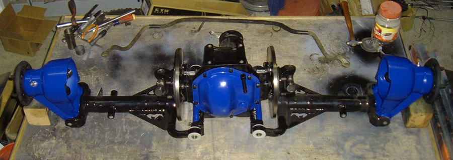
Here's an AC Cobra 427 lower.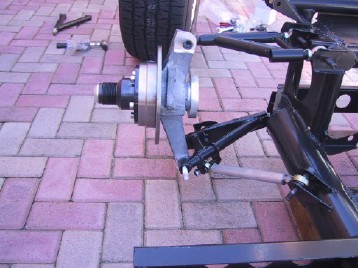
The forward link is outside the lower links pivot point by maybe 2". The frame tube is 4", your looking to the rear.
Here's Twin Turbo's copy of the same thing . He tried to adapt to a C3 Corvette. He's on Vettemod.com
Stop this video at 00:13 seconds and you'll get a good view.
Ralphy
Last edited by Ralphy (10/15/2012 7:38 pm)
![]() Offline
Offline
OK so I sketch like crap. Anyhow this is an image of a C3 Speedway Motors differential cover. My thought is to use a similar toe rod to the C4 and have it fully adjustable. I can slide the bracket up and down. I will lock the location by trapping the position with a second set of bolts and nuts aside the mounting stand offs. Then I can try different length toe rods and again position, then lock into place with a secondary set of bolts. The top tie plate will be drilled at only the proper location. I can make several tie plates at different locations. As of now my thinking is my toe rods should be approximately 1" longer than the HS's and 1/4" to 3/8" below center. Drawn location is probably not right. I think my heims would be further apart, outside the cover bolt holes. This is in conjunction with the KA T5 fore and aft links. I'm also looking to be able to move my differential fore and aft, up and down. I need to consider how different length HS's to toe rod affect any RS. I would probably have more meat at the radius than what I sketched. I'm looking to dial in as little roll steer as possible.

PT442, one main problem I see with trying to build something as you posted above. If you miss your mark, then what? We are not privy to a bank of $$$ and engineering. Seems we need a simple or somewhat adjustable approach. Phantomjock is building something that may take quit a bit of work. However his design would seem pretty straight forward.
Ralphy
Last edited by Ralphy (10/15/2012 10:22 pm)
![]() Offline
Offline
Oh my gosh! First off unless that link were one solid fixed piece at the upright, the HS will fold forward. Next the forward link is critical for how much roll steer you have. If you were to look at the pic I posted, it has a very long forward link..
The longer the link the greater the arc. The greater the arc the less roll steer you'll have since it pulls the lower less forward, bigger arc per inch travel. Now the location in and out. If the forward link went perpendicular to the lower, straight forward it would be at it's greatest point to pull forward. If you moved the link to the centerline of the lowers inner pivot you will have zero roll steer. So? The shorter and the further outward the chassis the forward link is, the greater the roll steer. Would you like to see a lower with roll steer built in?
Your not that far off!
My drawing is not at all to scale. The part of the lower arm that extends forward is in fact 22" long (center to center). And yes, the arm is one piece, like a large A-arm.
Here is a better, more to scale drawing of the lower arm. 
Note that the upright is attached to the lower in a similar manner as a stock Jaguar.
If you look at this picture, you can see how long that arm would be as it would be the same length as the factory lower trailing arm in the original solid axle setup.
Bill
Last edited by ProTouring442 (10/16/2012 1:24 am)
![]() Offline
Offline
More like a semi-trailing arm? I try to look at what the upright end does when you pivot it upright 90 degrees. Tells what it does in motion. The article states, "The BMW E30 chassis is blessed with semi-trailing arms for the rear suspension layout. The word "blessed" is used somewhat facetiously in this case. The semi-trailing arm suspension is not particularly well regarded among race car builders as it has a reputation for bad camber and toe changes during movement of the rear wheels. There is some truth to this. A semi-trailing arm arrangement is usually used because it's compact layout allows a lot of room for other things, like passengers and luggage, not because it offers superior chassis dynamics."
Seems you would have more of this since your inner point would be under the HS?
Ralphy
Last edited by Ralphy (10/16/2012 5:32 am)
![]() Offline
Offline
More like a semi-trailing arm? I try to look at what the upright end does when you pivot it upright 90 degrees. Tells what it does in motion. The article states, "The BMW E30 chassis is blessed with semi-trailing arms for the rear suspension layout. The word "blessed" is used somewhat facetiously in this case. The semi-trailing arm suspension is not particularly well regarded among race car builders as it has a reputation for bad camber and toe changes during movement of the rear wheels. There is some truth to this. A semi-trailing arm arrangement is usually used because it's compact layout allows a lot of room for other things, like passengers and luggage, not because it offers superior chassis dynamics."
Seems you would have more of this since your inner point would be under the HS?
Ralphy
Again, not exactly. LOL
On a Semi-Trailing Arm the upright is fixed where it joins the the arm. In my idea, the upright pivots where it meets the arm, just like in a C-4 or Jaguar setup.
Camber changes would be on par with those of the C-4 and Jaguar,.
It should have equal or less toe in during compression than a C-4 Vette.
Going back to my diagram...
The inner end of the arm mounts to the diff, like a Jaguar but with a Johnny Joint to eliminate bind.
The outer end mounts to the upright, just like a Jaguar (but with outboard brakes).
The forward end mounts where the forward end of the original solid axle trailing arm mounted (again, with a Johnny Joint to eliminate bind).
The upper control arm is the HS, just like a Jaguar or C-4 Corvette.
I think in the end I will just have to mock the thing up and measure everything to see how well it works... ![]()
Shiny Side Up!
Bill
Last edited by ProTouring442 (10/16/2012 5:57 am)
![]() Offline
Offline
Looking at it again. Standing the LCA upright 90 degrees. The rear would seem to come inside the front upright point giving toe-out. Your ill, you've got the IRS's disease. LOL!
Ralphy
![]() Offline
Offline
Looking at it again. Standing the LCA upright 90 degrees. The rear would seem to come inside the front upright point giving toe-out. Your ill, you've got the IRS's disease. LOL!
Ralphy
I don't think it will toe out on compression.... Damn it, I'll just have to mock it up! LOL
Bill
![]() Offline
Offline
Just take a piece of paper and fold it at the same pivot angle. Then fold it up and down, you can see which way the lower edge of the paper goes. If you raise the crease above, resembling the pivot point you will get toe-in it seems. Flat gives toe-out. If you raise the front point which resembles the forward pivot, seems you would increase anti-squat. Orientation will also change wheel base changes. Now these angles also change your roll centers and camber curve. This is where you start too hurl. LOL!
This is the same kind of thinking that made me see with twisting a LCA. Imagine a LCA with the inner pivots parallel to the road surface. Then cant the uprights centerline/pivot upward to the front. You will see the front point comes to 90 degrees before the rear points/pivot. The more you twist/increase the angle the more toe in you'll dial in. Even if the LCA is downward to the upright, it will toe in. The rear moves outward faster than the front since it's moment is lower again it moves outward faster. Take a rectangle piece of metal, twist it and watch the corner points.
Ralphy
Last edited by Ralphy (10/16/2012 7:56 am)
 1 of 1