
|
|
|
 |
 |
 |
You are not logged in. Would you like to login?

 1 of 1
![]() Offline
Offline
on June 9, 2010, 11:53 am, Daze wrote:
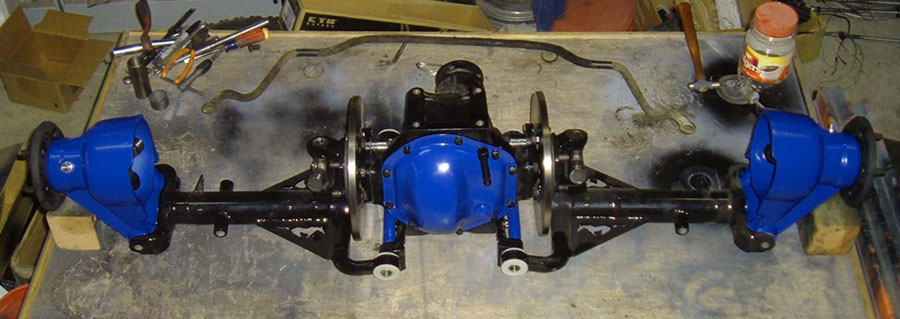
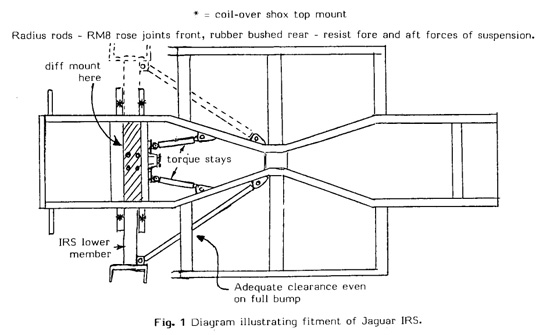
As promised here are some pictures of the parts I recently got that will allow me to maintain the correct pinion angle to match my transmission and also allow my suspension to travel vertically. The solution comes from three little letters XKE. I was going back through my loose leaf binder with the hundreds of pages of info I have gathered on independent rear suspension and one of the sections is several pages that came from CWI detailing all the differences between the various Jaguar IRS parts. One difference over the years has been the differential side brackets. They came in three different configurations: the XJ units were drilled to be parallel to the pinion, the 3.8S or saloon brackets were 3º down in relation to the pinion and the XKE brackets were 6º down in relation to the pinion which makes them parallel to the top mounting surface. By running XKE brackets I will be able to mount the diff 6º up and still have vertical suspension travel.
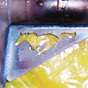
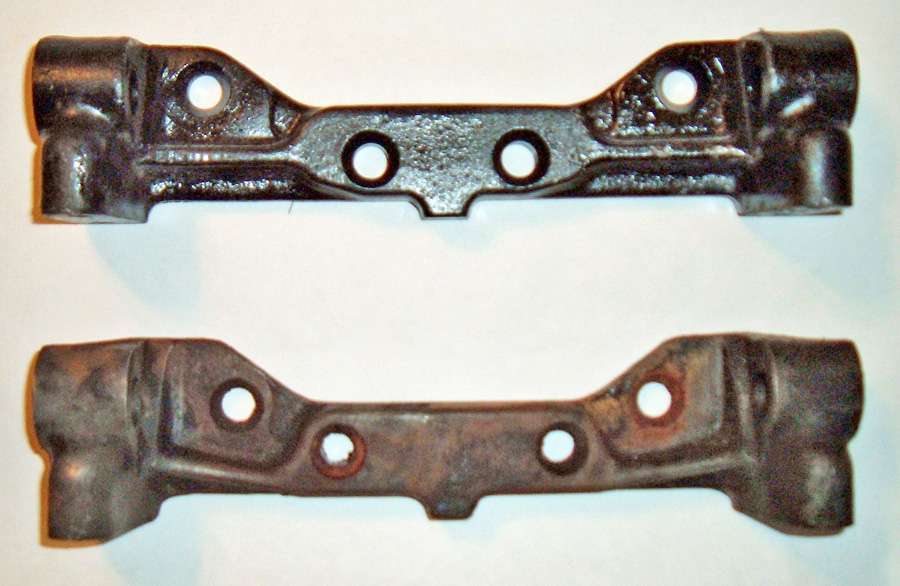
Here is a comparison between the two brackets. the top bracket is the XKE bracket and the bottom one came off of an XJ6.
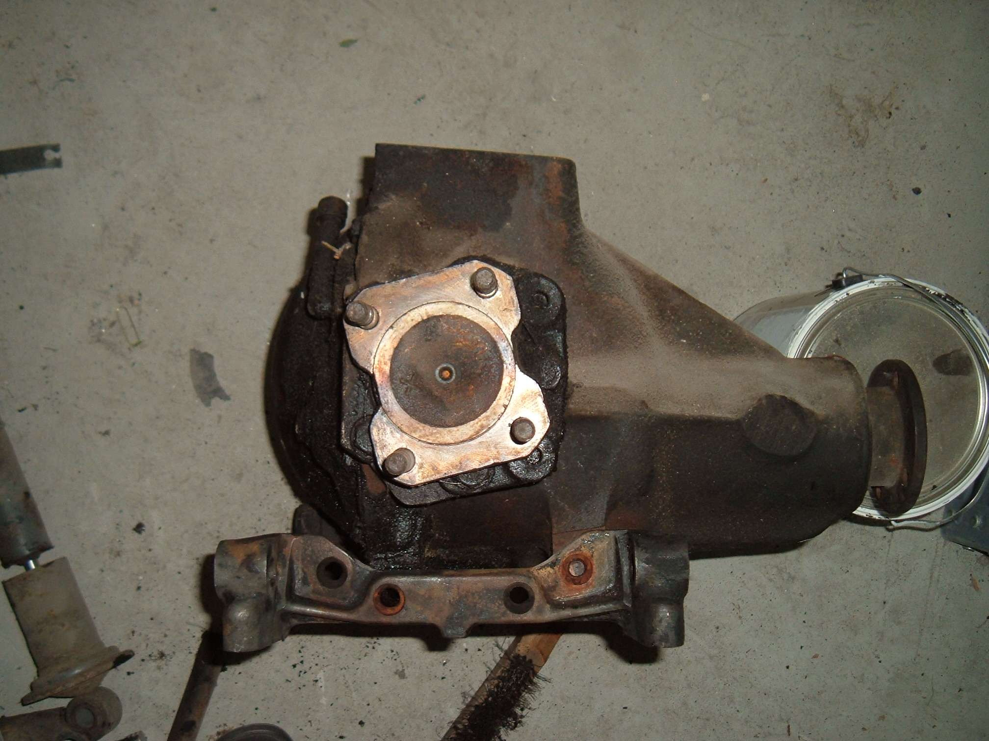
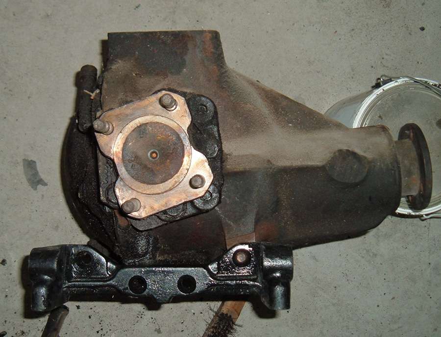
In this picture I have the XJ6 bracket on the diff and you can see how it is parallel with the pinion.
In this picture I have the XKE bracket on the diff and you can see how it is parallel with the top mounting bracket.
I have found several sources for these brackets, but In finding them I discovered that the jaguar community over the years has used them some what interchangeable and some suppliers didn't even know there was a difference. The easiest way to communicate the difference was to have the seller measure the distance between the center holes center to center. The Xj6 bracket is about 2 & 7/7" where as the XKE bracket is about 2" I can only assume that the 3.8S bracket would have holes that are half way in between these two measurements since the angle is half way in between.
Very nice job!! Sure beats all of the other alternatives and simple. Got to love simple
I discovered another huge advantage to these XKE brackets
With them, everything lines up!!! The center line between the top mounting holes, the drive axles, and the middle of the side brackets all line up. When I first drew up my upper mount using the XJ6 side brackets I had to take in to account the angles and off sets so that my crossbars lined up with my wishbone shock mounts and so the axle lined up with the middle of the wheel well allowing for some backward travel during suspension compression. with the new brackets all that is gone. I simply center the cross bars over the center of the wheel well, and then center the 4 mounting holes in relation to the cross bars and I am done!!!
Daze Very good info on Jag pinion angles. Very people know this. I have been looking for 3* angle brackets (Ithink from 60-69 3.8 S cars)for about 6 months, any info on suppliers? Thanks Dick
Welcome to the forum, Dick!!!! What are you working on??
We would love to see some pictures of your project and here more about it. You have three options that I know of. The first is machine the set you have. If you look at the brackets you have the back side has a flat machined surface that was the same for all three angles. I know CWI was welding them closed and then redrilling them. The second option os John Farrell---800-454-7977, he had the XKE units I was looking for and may have the S3.8 units. Your best option however is probably Dick Maury with Coventry West You will need to call them and ask for him specifically. They do not sell this part normally, but Dick is the differential rebuilder and has access to lots of used parts. IF you talk to him he can probably hook you up. Best way to describe them is to have the seller measure the distance between the middle holes. The Xj6 bracket is about 2 & 7/8" where as the XKE bracket is about 2" I can only assume that the 3.8S bracket would have holes that are half way in between these two measurements since the angle is half way in between. Let me know what you find and if I can help further.
(after I posted this I went through my emails and found one from Dick from when I purchased the XKE units, I went ahead and emailed him for you, I will let you know what I find out)
Daze Thanks I'm working on a 1932 Ford roadster (dearborn body) with a Kugel IFS and a Jag rear Dick
Heard from Dick at CW and he does not have any
I will continue to look and see what I can come up with.
My understanding the angle is needed to allow even wear on u-joints. Allowing the bearing in the joint to rotate at least one turn. Performance wise, zero is good.
What Say You!!!!!
It is my understanding that you want the pinion...
angle and output shaft angle to be parallel or off by no more than 2 degrees. The angle that you need is the pinion in relation to the driveline. in other words if the pinion was not only parallel with the output shaft, but also in line with it, there would be uneven u-joint where. tyrellracing is the forums drive line expert, I hope he chimes in to educate us all
That's approximately where I am now. When I lower my car it should be close to zero angle.
Me thinks when you get to such minimal angles, effects also are minimal. Equal angles and all really come into play with a solid axle third member. Whole lot more going on there, all that motion!
Not saying I will not try to keep everything all copacetic.
If you want some interesting reading on the subject check out these two threads from this forum
and
Just read over the posts and I think I already have a good understanding. Some other reading I have done, I had read a u-joint will premature fail with anything less then 3 degrees. But understand in our cases we are not working with daily drivers. Also velocity changes increase with the increase of angle and we have minimal angle. I had also read when dealing with minimal angles such as 2 degrees, vibration is about none. In my case I also have a 2 1/2" diameter 14" long drive shaft. With an increase of diameter you have higher velocities and more vibration. So my drive shaft/u-joints spin slower, so less vibration worries.
Velocity Charted At Various Angles
Even a 15 degree angle shows small velocity changes.
At a 60 degree angle the baseline equals 1 then reduces to .5 at 90 degree in 90 degree sweep velocity goes to 2. That equals a variation in speed of 4X, wow!
![]() Offline
Offline
Bringing this one back from the dead. I'm curious about the brackets. I'm building a 1946 International Harvester K3 Longbed. Using a front and rear out of an 86' XJ6. the front is rubber mounted like it was in the Jag. Also reworked the spring pockets and now have Slam Specialties SS 6 air bags installed. Onto the rear. I scrapped the idea of using the jag rear due to the 2.88 gear ratio. But, decided I have to use it in my build. i will just hunt down an XJ12 diff and use the pumkin with 3.55s if I can find one. I running a 63' 327/700R4 combo. I planned on angling the trans 3 degree down. As you know, the XJ6 pinion angle is 0 degrees. What should I do? I've read many times to run it like that as the Jag came the same way. Any thoughts?
Also, my plan all along was to rubber cage mount the rear as well, but now i want to uncage it. Is there a 100% prefered method for the crossmember, and other supports? I've seen too many ways and want to do it right. It's gonna be an everyday driver. Thanks for the help. Randy
![]() Offline
Offline

Randy if I'm reading you right. Your suggesting to run a 3 degree difference between the trans centerline and carrier. That is not the common preffered way. Both should be inline. Maybe the Jag carrier could suffer oiling problems? Three degrees is not a major increase. Maybe you could raise the gear oil height by installing a new higher plug?
Ralphy
And welcome to the IRS board
Last edited by Ralphy (9/07/2012 1:32 pm)
![]() Offline
Offline
Not sure you understood me. It's my understanding that the stock XJ6 came from the factory with the trans output angled down 3 degrees. The rear differential pinion angle was 0 degrees. So I have read over and over how it's common to just set it up the same way. I would think the pinion should be 3 degrees up to match the trans angle.
But that would angle the suspension as well. What is the suggested method?
![]() Offline
Offline
Your right I was not aware of that. Three degrees is not a lot, however zero is? The Jag guys here should be able to give you a better insight on Jag specific questions. My answer is based on a pure mechanical point of view. I've never seen any post suggesting different angles. If you go by the charts above it would seem three degrees is not going to affect the universals speed thru rotation much.
Ralphy
Last edited by Ralphy (9/08/2012 3:13 am)
![]() Offline
Offline
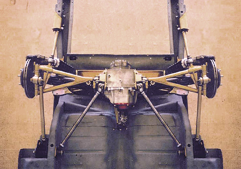
I was thinking the chevy engine /trans setup was closer to 5* with the carb plate/ trans pan level? The slick way to change the pinion angle on the jag is to come up with the LCA brackets that would come closest to your goal, especially if you are thinking a custom RA X member instead of the cage. Or you can get brave and weld in and redrill the brackets you have. ( I dont know how this is going to work in the long run yet) still a long ways to go for me to the road test. Minimizing the pinion angle I'm thinking would let you keep the RA mounted higher in the vehichle. Letting the bag system be a bit more dramatic looking when lowered. Here you might be up against clearance issues with the frame and such with the halfshafts/hub. This pic is to the extreme kinda because of a short driveshaft setup working with 5-6* angles under a straight frame and keeping the LCAs near level at ride hieght. But demonstrates the limitations of lowering/bags if the RA has to set low in the vehichle.
I'm pretty new at this stuff myself so I know I have left out a dozen or more things to consider. Would like to see some pics of what you are working on tho !
Edit: Tried the link but my feeble back-in-the-woods landline didnt agree with it,,lol
Last edited by Digz (9/08/2012 5:22 am)
![]() Offline
Offline
OK, first off I need to get with the lingo around here. RA = ??? I know LCA = lower control arms
I have the front Jag suspension mounted up and air bagged. I rubber mounted it the same way it was mounted in the XJ6 from the factory. The rear has been in and out of my truck several times. I wanted to use it but the thought of changing the gear ratio and rebuilding the suspension is just too much $$$. But in the end, I have to use it. There is a member of the HAMB website that is hunting down an XJ12 rear end and wants to swap with me. He wants the 2.88 gears I have in mine and figured he can just find the XJ12 rear with the 3.55 rear and we can swap so we both end up with what we need. Hot Rodders are good people! Anyway, I planned all along to rubber/cage mount the rear. When the cage and all is placed under my frame, the frame rails sit right in the rubber cage mounts. Very little fab work required. But, I've decided that I need to uncage the suspension and build my own Xmember and let this thing show itself. The truck is a long bed and I turned it into a tilt/dump bed so that I can raise it up out of the way so I can service the brakes easily.
As far as the Chevy motor and trans, it's yet to be mounted in the truck. I'm trying to sort out the front and rear suspension first. Get the truck sitting at the ride height and rake, then mount the 327/700R4 combo. I will be able to mount it at whatever angle I need.
Ive read that the stock XJ was able to get away with the different pinion and trans output angles because the rear was rubber mounted which absorbed any vibration if in fact there was any. Plus it used a two piece drive line.
Does Daze ever get on here? I would love for him to chime in. reading through the first post of this thread it sounds like the S/Saloon brackets would be my answer.
" They came in three different configurations: the XJ units were drilled to be parallel to the pinion, the 3.8S or saloon brackets were 3º down in relation to the pinion and the XKE brackets were 6º down in relation to the pinion which makes them parallel to the top mounting surface."
Never heard of that model Jag before. not sure if locating thos brackets will be easy or not. I'm also not bagging the rear suspension. Maybe in the future if the Shockwaves ever come down in price.
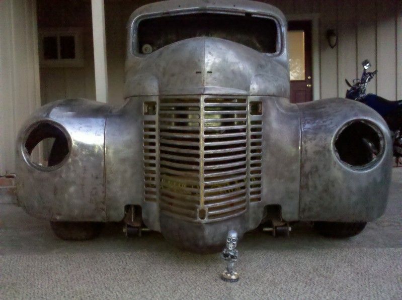
here is the front of my truck aired up, and aired down.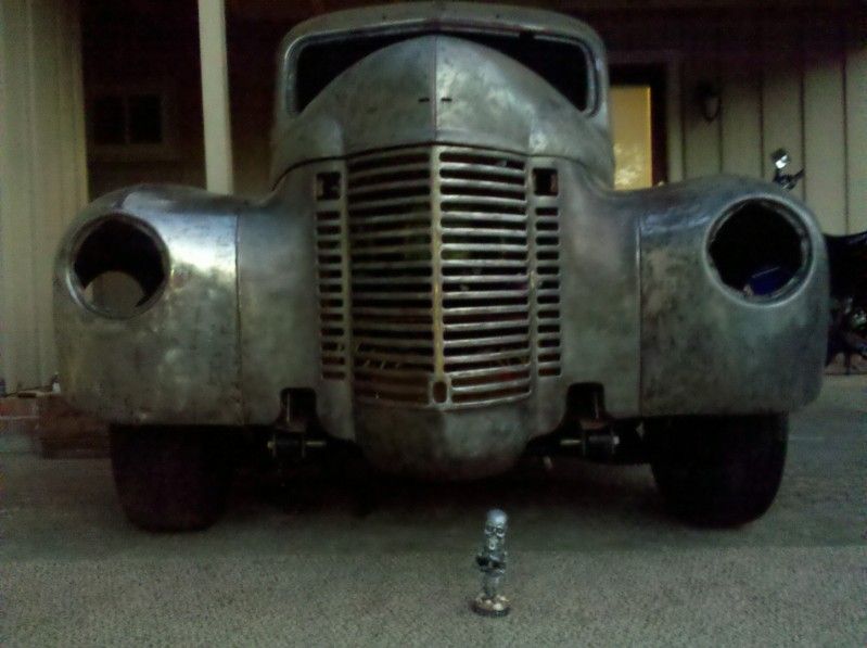
![]() Offline
Offline
So, one of the more more well known builders on the Hamb site is suggesting it will be better to use it how it is. Lift my pinion angle up 3 degrees to match my transmission's 3 degree down angle. Leaving the suspension with the positive caster to help reduce anti-squat.
Any thoughts?
![]() Offline
Offline
Randy,
Sounds like your getting some good advice at HAMB.So I'm looking at Day's posts, will this give you a LCA angle of 3 or 6 degrees? Not sure if your aware, because the differential is mounted solid to the chassis. An IRS does not give as much anti squat as a solid axle. You lose the added effect of the pinion trying to climb the ring gear.
Ralphy
![]() Offline
Offline
As it sits with XJ6 side brackets, if I install the rear differential with the pinion angle up 3*, the LCA's will also be tipped back 3*. Where as the side brackets from the XKE and Saloon models will allow the pinion to be set at 6* -3* while the LCA's remain level at 0*. XKE brackets = 6*/ 3.8s brackets = 3*
What I'm trying to figure out is if it's good or bad to have the LCA's tipped back like that giving the rear suspension positive caster. The LCA's sit level on a stock Jag.
![]() Offline
Offline
To me RA = rear axle assembly. I hear ya on the Shockwaves $$. Im gonna toss this in also. Your trailing arm set up might benefit some with a "little" angle on the LCAs if you end up going to the trans mount area in order to keep the In-line pivot points. The stock jag arms (and cage) are mounted pretty loose in big rubber bushings which I think lets it get away with alot of the bind that can occur. To me this would suggest quite abit of tolerance in small castor changes. Ive just been trying to piece all the stuff the more knowledgable guys here have put up together. Ralphy has a thread on Designed To Bind I think. Lots to read and absorb and try to adapt to swaps that are not the "Norm".
![]() Offline
Offline
of course I come to the forum. ![]() not as often as I have in the past but I try to get here as often as I can. I moved a couple of posts from the "old forum" that happened before the one you posted on. they have some good info and should help clear things up... or muddy the waters further
not as often as I have in the past but I try to get here as often as I can. I moved a couple of posts from the "old forum" that happened before the one you posted on. they have some good info and should help clear things up... or muddy the waters further ![]()
Ultimately when I did mine I decided I wanted to do what ever I needed to to get the LCAs moving perpendicular with the road (as Jag designed) but also match my pinion angle to my trans angle (not a Jag designed) the reason for this is the LCAs were functioning as Jag intended them. All of there models (using the original IRS design) had the LCAs moving perpendicular to the road regardless of pinion angle. I decided to not set my pinion at 0º because the difference between the trans angle and a 0º pinion was just o much at 5º. I think 3º is acceptable but barley. getting the trans and pinion angles closer to parallel will always be more ideal.
As to the S/Saloon bracket, they would be a fantastic solution to your problem however finding those brackets will be extremely difficult. I once spoke to Mike at CWI when they were still in business and he took XJ6 brackets welded the holes closed and redrilled them at the correct angles. I find that to be an acceptable option, but a better one IMHO might be to fabricate brackets from scratch with the correct design. Further more I think you are going at this a little backwards. You really need to get the engine and transmission in so you know what kind of angle you truly need before you mess with the pinion brackets. What if you have tones of room and can get the transmission closer to 0º or what if there is not much room and you angle is closer to 6º in either of those cases you will need to rework the rear end angle to make it correct.
![]() Offline
Offline
See there you go muddying the waters with facts! LOL! I totally overlooked the fact if you change the angle of the LCA's it will impact the function and location of any radius rods/trailing links. Welcome to the IRS Rubics Cube! ![]()
Ralphy
![]() Offline
Offline
I just read through all the threads brought back from the dead. Yes, the water that was starting to clear up is now muddier than ever ; ) As far as the motor and trans go, I just feel I need to get my ride height set proper in order to mount those. I'm just not sure of the ride height without the rear installed to see how it will sit. I guess I could do a temp crossmember for the Jag rear to put it in place. Remove the coilovers and install a spacer to hold the suspension/half shafts at ride height/level. Then after the motor and trans are mounted, move back to the rear to figure out the pinion.
As far as the way I will install the Jag rear, radius rods/trailing links........ no clue yet. I've got a folder on my pc with so many different ways to do it my head spins.
As far as my engine/trans go. I do have a lot of room and should be able to install it with whatever angle I need. But I've always read you want 3*-5*. That 0* is not good at all. So if I was able to level the transmission with no angle, then set the Jag rear in keeping it all level the way it was in the OEM car..... wouldn't that be bad for the Ujoints??? I know there would be a little angle from the pinion being offset a little to the passenger side, but I may be installing the engine a little offset as well to clear the steering linkage.
I tried looking around the site for a thread of your install, do you have a thread with photos? And is there a true, 100% agreed upon way to uncage the Jag rear? As far as the crossmember design, coilover mount design, radius rods/trailing links design?????
![]() Offline
Offline
Randy,
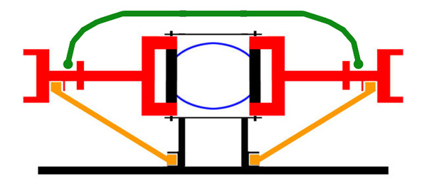
OK I think Day is right, start with the motor and trans first. Pinion and drive shaft angle? I think your confusing two different things. The trans shaft and pinion should always be in the same plane zero two parallel lines. Now that does not mean you would draw an imaginary line straight thru the two, only parallel. Then the 3 to 5 degree U-joint angle. in order to accomplish this is to have the differential above, below, right or left. Or a combination below left or say below right, etc... As you said it's the opinion that a U-joints will fail if they have zero motion thru rotation. Plus being a IRS there is no motion between the trans and diff. unlike a solid axle, they are both fixed.
The second in the illustration is common.
Trailing links or arms? Visualize your suspension parts moving in a circular motion a circular motion being attached at one end. A trailing link that pivots at the wrong point can pull and bind, even break!
The below examples are a binding deign.

This design thru motion will pull the LCA forward causing a toe-in effect. The toeing causes what is called roll steer. Toeing in is better than toe-out on a rear suspension. However this design also binds. Some do not.
In order to brace and strengthen a LCA with a link? Remember this, the link has to be inline with the LCA's inner pivot points exactly in line in all planes. Below are examples of a few. Day's pic is such the example also.

Here's a non binding going to the rear.
Last edited by Ralphy (9/09/2012 8:01 pm)
![]() Offline
Offline
Thanks for the info. Anyway you can show me the proper ends to use. That way I know what to hunt down. My truck is a long bed/wheelbase K3. I can go as long as I need on the Radius Arms. 50"-60" long would be easy. That would put them right at the base of the cab. The trans crossmember will be about 6 feet from the LCAs so I can add a crossmember anywhere in between. Maybe with a drive shaft loop. Is there an optimum length? My exhaust is gonna exit before the rear tires so that won't be an issue.
What is preferred for the torque stays? Straight ahead fixed where the radius rods connect like the photo to the rear you posted, or at an angle connected to the frame rails? And what should I use for those ends and what size tube?
Ive always heard that a driveshaft setup in perfect alignment won't allow the ujoints to lubricate themselves. Guess I will be attempting to mount the motor and trans level!
![]() Offline
Offline
Phantomjock put together a page that we added to. It contains bits and pieces for a build.
Aurora makes some good quality spherical bearings.
PJ's thread, Bits and Pieces - COMPONETS for your Build
Aurora
As far as a preferred location of a trailing link, I would say it's not to the rear. Being I have a Cobra and speaking from experience, I would say going to the rear may be a little out of necessity on a Cobra. There's not a whole lot of room to go forward on these cars at times. As to preferred location again hmmm........ Depends on what you're trying to accomplish racers, that is racers who go thru turns today prefer to remove any anti-squat. As it adds to performance/traction in a straight line. Throttle and braking in turns cause adverse effects in turns. Not big effects, however racing applications have a need for any advantage. If you have ever seen a NASCAR Sprint Cup Car. They use what is refereed to as truck arms. These arms go way forward and as close to the middle/center of the chassis as possible. This allows the suspension to work as freely as possible without any torque effects. OK so I said forward. The longer/forward you mount your trailing arms, the less anti-squat you will have. Trying to lift a car from the middle is way different than lifting from the rear. If you ever jacked a car up I'm sure you know what I mean. So not only does the angle of your LCA create ani-squat, so does the mounting position of your trailing links. Now I'm guessing your building a street car? I would also guess you may want a little anti squat or lots! You like that street light drag racing!
Modern day cars, gone are trailing links out with links in with double wishbone. True LCA ans UCA are the common staples of modern OEM cars. Why, first off if you break a halfshaft, being that it's a suspension member a whole lot of bad can happen when that corner falls. Second the amount of anti-squat is fixed having no fore or aft links changing angles thru motion.
Remember I said some suspensions can bind and cause roll steer at the same time? Here is an example of an IRS that roll steers with no bind The Corvette C4. Notice the toe link behind the half shaft. Notice the toe link is longer than the half shaft. The toe link moves in a much larger arc/radius than the halfshaft. So when motion is applied to the suspension the halfshaft moves inward faster than the toe link. It has a smaller radius arc. Toeing in the rear tires, it's been many posters belief this was as much added as a safety feature by GM. So if you were to over throttle in a turn and the rear gets away. The less out of control the car will get. The modern Mustang and C5, C6 Corvette also use a toe link with a double wishbone.
Ralphy
Last edited by Ralphy (9/10/2012 6:25 am)
![]() Offline
Offline
Pulling this from another thread bumped to the top. Would a double cardan u-joint help or hurt with any of the bad driveshaft angle setups Ralphy shows in his pics?
![]() Offline
Offline
A double can be made to work but the logistics of setting one up is a little more challenging. In order for a double cardan to work correctly the u-joint on the single cardan end of the drive shaft must be perpendicular to the pinion or transmission output. in other words the drive shaft needs to be in line with the either the transmission out put or the differential (depends which end it is on) and there needs to be no angling at the u-joint. This brings us right back to having to adjust the pinion angle at which point you can set the pinion parallel with the transmission angle and run a single cardan. Double cardans are common on lifted trucks because the live axle can be easily rotated to get the pinion angle in line with the drive shaft.
![]() Offline
Offline
I almost went with truck arms on my build. I scrapped the Jag rear because of $$$. The 86' XJ6 rear I have will need to be gone through and also it needs a different gear ratio. So I decided on an Explorer 8.8 rear with 3.73/trac-loc/disc brakes. I had it sitting here so it was a cheaper way to go to get my truck on the road. The truck arms were my first choice. Then I thought about it and didn't want to spend a bunch on the setup as it would all be swapped out down the road for the Jag rear anyway. So I was just gonna make it simple and use the leaf springs from the Explorer. I picked up a set of Liquid Iron Ind. Leaf Spring Sliders to use rather than shackles. Thought it would be different and a little cool. Plus it helped keep the rear low. Then a member on the Hamb site offered to buy an XJ12 rear with the gearing I need and swap me for mine which has the gearing he wants. He may or may not come through on the trade, but it planted the seed in my head to just go with the Jag. If I don't get to trade it for what I need I will just need to have new gears installed, find a proper geared pumkin, or another complete rear with the right gearing. I've got time.
Yes, it's gonna be a street car/truck. I plan on it being my everyday driver. it's a long bed with a wheelbase of 130"-132". The bed is 8.5' long. It's a long truck! I've got the Jag IFS rubber mounted and airbagged. All the mounts in the front for the suspension are just tacked on. I may end up removing them and weld the Jag crossmember solid to the frame. My plan with the rear was to cage mount it with the factory rubber mounts. My frame rails fall right in the mounts. Then both the front and rear would be rubber mounted. But now I want the rear to show so I'm now thinking the front doesn't need to be rubber mounted either. To be decided.
I have a C5 Corvette so I know the rear suspension pretty well. Thanks for the links and info. Much appreciated.
![]() Offline
Offline
So is it the Heim joint ends I'm looking for? I guess what I'm looking for is what ends are gonna fit the Jag LCA mounts and what ends am I looking for to use at the other end of the radius rods?
Then am I just looking to use Clevis ends for both ends of the torque stays? Is it a benefit to run torque stays on the front and rear of the differential?
![]() Offline
Offline
Randy if I'm reading you right. Your suggesting to run a 3 degree difference between the trans centerline and carrier. That is not the common preffered way. Both should be inline. Maybe the Jag carrier could suffer oiling problems? Three degrees is not a major increase. Maybe you could raise the gear oil height by installing a new higher plug?
Ralphy
And welcome to the IRS board
IF YOU WANT TO GET MOREOIL IN THE DIFF EITHER FILL IT FACING DOWN A HILL OR JACK THE REAR OF THE CAR IF YOU PUT A PIECE OF 3/4 PLY UNDER EACH WHEEL YOU COULD KEEP THE OIL IN THE DIFF CONSTANTAT A LATER FILL.
1 of 1