
|
|
|
 |
 |
 |
You are not logged in. Would you like to login?
![]() Offline
Offline
What: MN12/FN10 ('89-97 Thunderbird/Mark VIII) rear suspension.
Where: Underneath a '64 Ford Country Sedan.
How: Trial fitting indicated that the subframe nestles in pretty well, might require minor floorpan mods in a couple spots (though I'm trying to avoid that.) The front legs need a bit of alteration to locate properly on the frame rails near the base of the axle kickup. I'm retaining the factory rubber subframe mounts and hats (examination of several junkyard units and the two sets I have as parts indicate that the mounts in the subframe age pretty well, but the upper mount hats wear.).
Most likely that the stock fuel tank will not be usable, will require fabricating a tank to nestle under the driveshaft in front of the rear suspension similar to what the MN12 cars used from the factory, and as is typical on many other newer cars.
Stock shock location will not work, plan is to modify the aluminum FN10 Mark VIII lower control arms for Bilstein coilovers with upper mounts on the main frame rails.
Many details still being sorted. Iron Thunderbird SC 8.8 3.27 Trac-Lok pumpkin with late Explorer rear cover, modified late GT500 2-piece driveshaft and center bearing., stock 'Bird SC axles for now.
I've got a couple poor pics of the mockup process I'll try to post later. Subframe is off being sandblasted pending completion of the front leg and pumpkin mount fabrication work.
Last edited by JEM (10/10/2011 3:21 pm)
![]() Offline
Offline
MustangSteve's forum, my Galaxie forum... and now here, I think you must be following me. ![]()
![]()
![]() Good to see you over here, welcome to the forum!!!!!!!!
Good to see you over here, welcome to the forum!!!!!!!!
You project sounds like a lot of fun, I can't weight to see the pix. What made you decide to go t-bird/ mark VIII suspension?? How does the track width compare to your 64?? I am just excited we have a fresh project on the forum and cant weight to here more.
![]() Offline
Offline
Daze wrote:
What made you decide to go t-bird/ mark VIII suspension?? How does the track width compare to your 64??
Because it's there...
It's a fairly modern design and looked reasonably easy to adapt, relative to frame clearance and mounting and etc. Maybe not quite as easy as a Jag X300.
The width over the hubs is about 2.5in wider than the stock axle if I recall correctly. I have measurements around here somewhere. The American Racing style 427 wheels (18x10 in back with 285/40-18 tires) were made with what measured out at the time to be the correct offset for the MN12 IRS. If I had to do it over again I might try to pull them in another 1/4in. There's not a pile of clearance but it should be enough.
The subframe being prepped for the car came from an early Thunderbird SC. I also have a '95 Lincoln Mark VIII unit that's been cut up for various measuring and jigging purposes.
Learned while cutting that while the subframes are dimensionally identical the '89 Thunderbird SC subframe has an extra 1/8in steel channel inside the front crossmember that the '95 Mk8 subframe does not, though in this case that's academic since the cuts to the front crossmember are going to require external bracing.
Last edited by JEM (10/12/2011 7:44 am)
![]() Offline
Offline
Because it's there...
Nothing wrong with that answer ![]() Those systems are good ones. I always like to se why people chose one IRS type over another. The all have different positive aspects as well as different negative aspects so it is always interesting to see if there was a specific design aspect that made a person choose one of the other.
Those systems are good ones. I always like to se why people chose one IRS type over another. The all have different positive aspects as well as different negative aspects so it is always interesting to see if there was a specific design aspect that made a person choose one of the other.
Are you going to run the stock bushings on all the moving points or upgrade to some of the hard bushing kits?? I have heard those kits make a huge difference in performance handling
The width over the hubs is about 2.5in wider than the stock axle if I recall correctly.
So that puts it some where in the neighbor hood of 64.5"??? I know that wheel flange to wheel flange on my 62 Gal is 62" and I am assuming it is the same on your 64. 64 is still a leaf spring car right?? I know they had coils in 65 but not sure about 64.
I can't weight to see some pix!!!!!
Last edited by Daze (10/12/2011 2:11 pm)
![]() Offline
Offline
Are you going to run the stock bushings on all the moving points or upgrade to some of the hard bushing kits?? I have heard those kits make a huge difference in performance handling
No, I'm running the stock bushings, at least for now. In the past I've gone down the road of stuffing harder bushings in everywhere and paid a massive NVH price for it. I ended up having a set of aluminum bushings made for the subframe mounting points to be able to properly jig them, so I have them if I want to try rigid-mounting the subframe.
I've got an Explorer rear cover that resolves all the weaknesses of the factory beer-can-thickness rear cover and mount, and am working on fabricating a mount for it. The Explorer carrier mounts more typically German - a single offset front mount with a pair of widely-spaced rear mounts. Mine's something of a hybrid, with the iron 'Bird front case and the Explorer cover, it'll end up a four-point mount. Biggest problem is that the width of the ears on the Explorer cover as they fit in between the rails of the MN12 subframe preclude use of the stock Explorer rear mounts in the same position they're used in the Explorer; I'll be using a pair of E38/E39 BMW rear mounts (which are also very slightly cheaper...) on a bracket that spaces them in an inch on either side.
So that puts it some where in the neighbor hood of 64.5"??? I know that wheel flange to wheel flange on my 62 Gal is 62" and I am assuming it is the same on your 64. 64 is still a leaf spring car right?? I know they had coils in 65 but not sure about 64.
The '64 9-inch is 61.25 axle flange to axle flange. The IRS is just on 64 inches.
Got the legs jigged and some filler plates tacked in, then hauled the thing down to the ace welder. I'm too out of practice, and don't want to booger anything up too badly. Was in too much of a rush to get it to him to get any pics, but I'll be taking plenty of the trial-fitting and etc. Won't have it back for a few days.
Last edited by JEM (10/20/2011 1:53 pm)
![]() Offline
Offline
I know you need to weight for the parts to come back from the fab shop for new pix, but what about the "poor" pix you promised to post for us???
![]() Offline
Offline
Hi JEM, hi Daze,
Has been a long time since being here but hope that I can come in more then in the past!
JEM, I had the oppertunity to get a Thunderbird IRS but after looking to it I tought it will raise the rear of the car a little because of the upward pointig arms. Even when cut they might lower the cage which will raise the rear of the car to a level that's to high for me! This was just eyeballing and not meassured but seemed like that visually. Do you have pics of your setup? The TB IRS is still available and mighht be a future plan.
Mustsed
![]() Offline
Offline
I know you need to weight for the parts to come back from the fab shop for new pix, but what about the "poor" pix you promised to post for us???
I thought they were in my phone, but I'm having a hard time finding them...
![]() Offline
Offline
JEM, I had the oppertunity to get a Thunderbird IRS but after looking to it I tought it will raise the rear of the car a little because of the upward pointig arms. Even when cut they might lower the cage which will raise the rear of the car to a level that's to high for me!
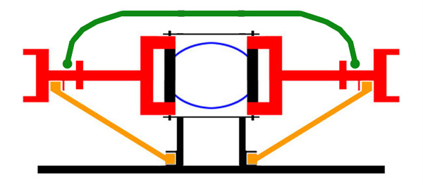
My rear arm-orientation technique is a little brute-force, but it's basically clamping a bar under the control arms to keep the bottoms of the airbag pockets in the Mk8 arms parallel to the ground. Since they're angled slightly relative to the arms, this results in the arms being angled downward just over 1in from the inner to the outer pivots. This is close enough to my eyeballed evaluation of MN12 'Birds and FN10 Mk8s on the road and should work fine from a suspension-geometry standpoint. I can shim this support bar under the lower arm inner pivot brackets as necessary.
Yes, this means you have to get the subframe WELL up under the car, and depending on the vehicle involved it may not be possible. The fabricated crossmember to support the rear subframe mount bushings ends up being a downward-facing C-channel mounted flush with the tops of the frame rails, the bushings nestle up in the mouth of the C between the frame rails. I'm still hoping I can get away without cutting on the body floorpan in this area, the clearance will be ~3/8in in some places. As noted, the front legs had to be reconfigured to get them a little further down the kickup part of the frame rail in front of the axle. I'm planning on picking up a Jag XJ40/X300 assembly at the next junkyard half-price day, just for comparison purposes.
I'm not really trying to lower the car from stock ride height; if anything, the rear may end up being an inch or so higher than the original Ford spec. All the pics and drawings I've got of these cars in stock trim show them slightly down at the back, but my ride-height measurements are based on some of the '63-'64 Ford and Mercury NASCAR cars and clones thereof; they're typically 8in from front crossmember to ground, with approx 1/2-3/4in of rake from the frame rail behind the front wheel (6in approx to ground) to the frame rail in front of the rear wheel (6 1/2-6 3/4in).
Last edited by JEM (10/21/2011 9:50 pm)
![]() Offline
Offline
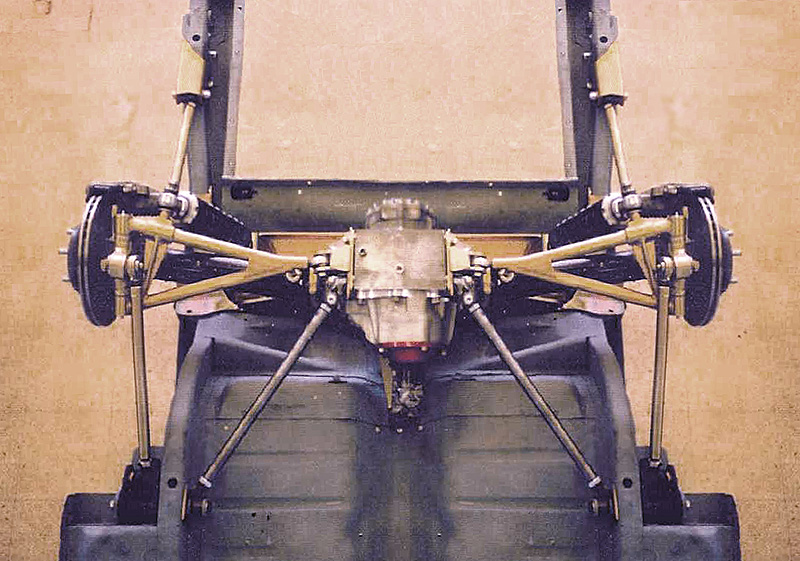
Back from the welder, partially assembled for trial-fitting, a couple pics:


The car needs to come down a bit over 2in from the point it's sitting at in these pics, and this trial fit was just intended to:
a) confirm the mounts would end up where I want them to end up when at the proper ride height, and
b) determine the proper fore-aft position of the wheel/suspension/subframe.
The 2x4 bolted to the bottoms of the spring pockets in the lower arms is just to keep the arms at approximately the right ride height, note also the welds on the front legs of the subframe where small wedges were removed from the arms and the arms bent to move the mounting points down a little under 2in (which also resulted in them moving inward and rearward just a bit, which will help them line up better under the car's frame rails anyway...) I'll template and cut some doubler plates to go over the welds. The welder was a bit surprised at the poor quality of the factory welds on the subframe, there's some places that need to be fixed and reinforced.
Once I know it fits where it needs to fit the frame will come back out from under the car both to get the mounts on the frame rails and to set up the front end (installing the mounts for the Gearheads upper arms, checking ackermann and bumpsteer with the arms and the ZF steering box and fiddling the box and idler locations as necessary, maybe sorting the engine mounts.)
The aluminum subframe mount bushings are to preserve alignment of the frame mounts during installation; I'm not planning to run them once the mounts are welded up and the subframe is in the car.
Last edited by JEM (11/14/2011 1:13 pm)
![]() Offline
Offline
Thats really cool, thanks for the pix. so it looks to me like the mounts are up against the frame??? if so how do you plan on dropping it the 2" needed to get the ride height where you want it?? Also are you going to replace the UCAs with tubular units or run what you have?
![]() Offline
Offline
Thats really cool, thanks for the pix. so it looks to me like the mounts are up against the frame??? if so how do you plan on dropping it the 2" needed to get the ride height where you want it?? Also are you going to replace the UCAs with tubular units or run what you have?
No, there's no less than 2.5in between mount and frame anywhere. The only point of probable contact (well, certain contact) is between the fore-aft rails that retain the upper arm pivots and a transverse sheetmetal rib on the floorpan of the body against which the old gas tank seated. I will probably just chuck the spotweld cutter in the drill and remove the entire rib. The rear mounts are actually inside of the wagon frame rails, I'll have to fabricate a crossmember to pick them up, but that crossmember will have to be profiled to clear the floorpan where it drops down between the rails in the middle.
As for the upper arm, no, the stamped piece will be fine, it's strong enough and reasonably light. If I were going to do anything I'd just cut up a second set of arms to make some reinforcements.
Last edited by JEM (11/14/2011 6:26 pm)
![]() Offline
Offline
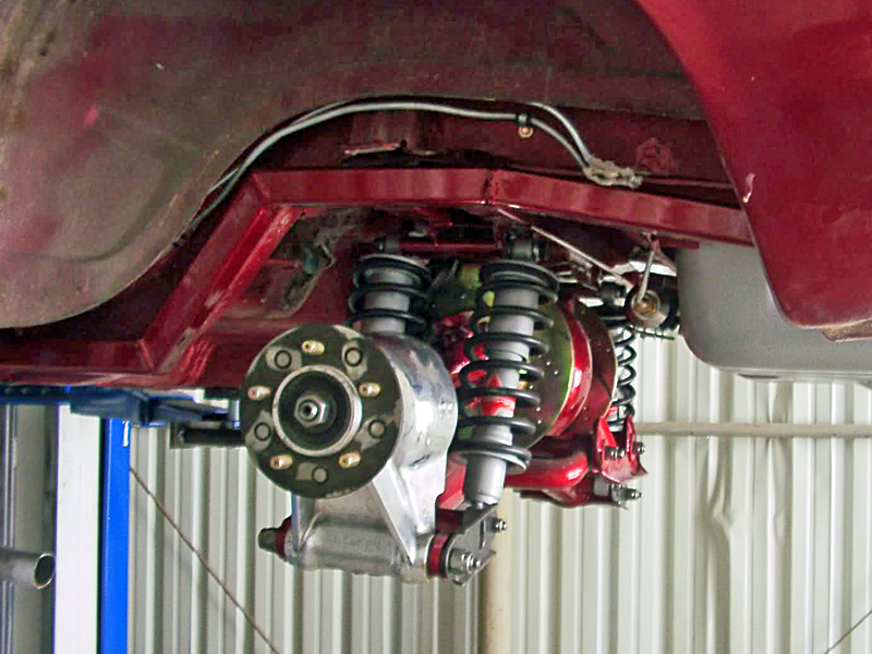
Just to clarify, a few more pics taken with a real camera (phone cameras may have all the pixels in the world but most have godawful slow shutters and trying to find the shutter 'button' on a touch-screen when you're holding the thing at arm's length under the car...bah!) 

The distance from aluminum jig-mount to frame rail is clearer (the left-side front you see in the pic, because the car is sitting lower on the jack on the left side than the right, only needs to come down a bit over 1in) and you can see the ~1in between the fuel-tank rail and the upper rail of the subframe.
The pic makes the tubular crossmember look much closer to the subframe than it is, I've got ~3.5in to play with there. I am shifting the subframe back (lengthening the wheelbase) approx 0.5in to ensure enough clearance between the front subframe crossmember and the footwell/underseat depression in the floorpan in front of the "axle".
All that flash-rust on the weld metal came from sitting outside over ONE foggy night while I was exercising my mad Sawzall skills chopping up the bones of an impressively rusty parts Cortina, but that's another story.
No Jag IRS for the Cortina, thought briefly about trying to replicate what Colin Chapman did on a couple prototypes adapting an Elan strut IRS to the 'tina body, decided it was way more work (not to mention $8k in parts if you buy repro Elan rear suspension bits) than I wanted for that car so I'm going to find an 8in stick axle for it, transplant the upper trailing-arm brackets ('tina GT rear suspension's a fair bit better than the leafspring norm) and try, somehow, to get a set of Euro Mk3 Capri 2.8i monoleaf rear springs over this side of the pond for it.
Last edited by JEM (11/14/2011 8:51 pm)
![]() Offline
Offline
Those pix are much better, thanks!!
![]() Offline
Offline
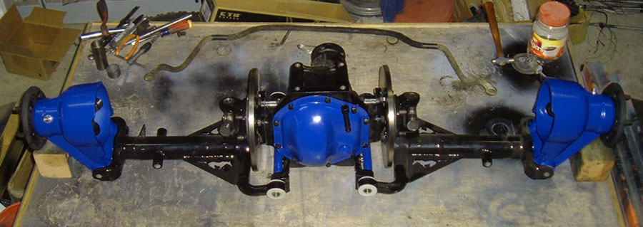
Progress!!!!
The modified MN12 IRS is hung on the frame now, it's bolted up under the car, and it's been sitting on its wheels. A little bit of proof:
Modified MN12 subframe bolted up to '64 Country Sedan frame. Front mounts and rear crossmember tacked in place. Subframe bolted up using aluminum solid mounts I'd had made for setup purposes; when it's done I'll go back to the original steel-hat-with-rubber-insert mounts. The crossmember had to be very thin vertically because the body floorpan hangs down between the frame rails at this point, the ends are a downward-pointing C-section that saddles over the mount bushings. Fairly shallow (3/4in vertical ribs on the front/rear) but thick material (cut from 3x6x.250 steel) and ribbed on the underside around the mount bushings. Maybe overkill, but...
The 8.8 pumpkin in this assembly is a scrap Mark VIII aluminum housing - the local pick-n-pull most often drains rear axles by punching a hole in 'em, and this one they managed not only to puncture the rear cover (about which I didn't care) but bugger one of the bearing caps in the process. 'Sokay, when it all goes together I'll be using the iron Thunderbird SC case anyway.
The pumpkin has an '02 Explorer rear cover (infintely more solid than the stock beercan-gauge early 8.8 rear cover) but the wings on the Explorer cover are too wide for a decent-sized isolator to clear the side rails of the subframe. So the rest of the mount consists of a piece of C-channel bolted to the Explorer cover wings, and a pair of E38/E39 BMW rear diff mount bushings pressed into a fabricated steel mount assembly that bolts to the subframe. We'll see how it all works out.
The '02 Explorer rearend assembly is an 8.8 and much beefier overall than the earlier units but very different in shape and critical dimensions; the axle shafts, side bearings, etc. are all different and it would not have been easy to adapt. 
This is what it looks like from underneath. Had to remove the front gas-tank mounting rib from the body floorpan to clear the upper subframe rails. The whole thing is bulky enough that the stock gas tank isn't gonna fit, no way, no how. Planning for a flatter welded-aluminum tank in front of the subframe under the driveshaft - this is what the MN12/FN10 cars did, and what a lot of other modern cars do. Haven't decided yet whether to do a smaller tank behind the rear subframe too; might be able to get 35 gallons total if I do. Regardless, plumbing the filler, etc. is going to be interesting. 
Ride height here is 6.75in from ground to the frame rail at the rear cut-line of the back door. Looks pretty good. 285/40-18 tires don't look all that big once the thing's on the ground.
The frame will be coming out at least once and possibly twice more to finish the welding, get rid of some of the original Ford stuff, etc.
Last edited by JEM (7/30/2012 2:17 pm)
 1 of 1