|
|
|
 |
 |
 |
You are not logged in. Would you like to login?
 1 of 1
![]() Offline
Offline
on September 28, 2010, 10:34 am, Daze wrote:
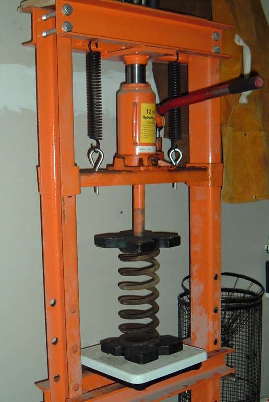
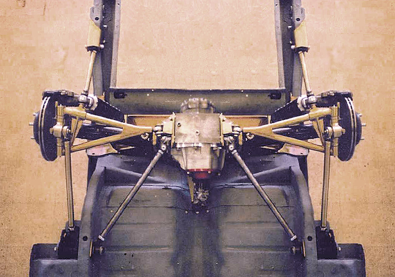
I too am not very happy with the Jaguar OEM spring rate. They are just not quite stiff enough when angled and there is not enough room to decrease their angle by much. With that in mind I wanted to find some replacement springs, but before I could look I needed to know what the OEM units were rated at. To that end I decided to set up a little experiment. Springs are rated in lbs/inch in other words how many pounds of pressure does it take to compress the spring 1". To find out I grabbed a bathroom scale I had purchased for similar tests in the past and set it up on my shop press. I added a steel plate to the top and bottom zeroed the scale and then cranked the press so that it just barley made contact with the top plate.
From there I marked 1" of travel on the sides of my press and began to slowly compress the spring. I watched the scale as the spring was compressed and stopped cranking on the press when I had compressed the spring 1" The magic number was 195#. Being that they were use I would be willing to bet that a new set of OEM units is rated at either 200#/" or 35KG/centimeter depending on how they were originally rated and both numbers where calculated using the 195 and then rounded up to the nearest whole #
With that data a pair would have the rate of 400# if mounted vertically, but at the approximately 35º angle they are mounted at they are only 65% effective making a pairs effective rate 260#/" no wonder they feel so soft!!!
With this info I went looking high and low for a set of replacement springs but could not find anything. All of the aftermarket options have an I.D. no larger than 2.625" and the jag units require a 2.875" 1.D.
At this point I am stuck with the OEM units but I got to thinking what if I added a 1/2" spacer to require the spring to be further compressed when the shock is fully extended. this added preload should add more stiffness to the springs. best part is it can easily be done by using the retainer off of an old set of OEM shocks. it fits nicely on the KYB retainer and a spacer ring could easily be used between the old and new sleeve to help transfer the load better. Requiring 1/2" more preload should make them stiffer, but by how much I am not sure. I am also not sure how much the original preload plays in to the effective rate. I know an OEM spring has to be compressed a little over 1" to be installed on the coil over so obviously that would increase its effective rate as well.
What is the compressed length of your OEM coilovers at ride height when installed on your Mustang? Do you know the corner weights of your car?
When I mocked it up...
I was some where in the neighbor hood of 1" however the coil spring was already compressed 2" to get it on the shock. As far as the corner wight I can only guess. Last time I weighed my car the curb weight was 2575#. which would result in a 1545 front weight and a 1030 rear weight making the rear some where in the neighborhood of 515 per side.
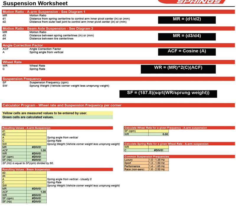
I wish you had posed all the math stuff you sent me especially about the effective spring rate being incorrect because the cart I was working from was for a live axle. It was fantastic info!!! right after I got it from you I got an excel work sheet from a spring company that takes in to account the exact info you sent me, figures in leverage, AND does all the math for you, all you have to do is plug in the numbers. here is a jpg of it.
I dont see any reason why the front suspension info can't be used to calculate the correct spring rate.
Hi Daze. I will post the e-mail I sent you off-line, but I want to preface it by saying I am not an expert on suspensions. I'm just an old Mechanical Engineer and I'm learning along with you. I wanted to get you thinking and you've come up with some good support for a math approach. Awesome information, Thanks.
Here's the e-mail:
'I read your thread about measuring spring rate. Your 200 lb/in number is probably pretty close. I've never been able to find the stock spring rate published anywhere. I'm assuming you got the .65 correction factor number from the table in another thread that you started "So what do you guys think of my idea to make the top shock mount...."
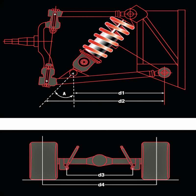
I disagree with this table. The diagram shows a solid axle. In which case, the static load correction factors should simply be the cosine of the angles in the table and they are not. I have seen other tables on the internet that show a lower control arm 16 inches long with the spring load 14 inches out on the lever, and they show the same correction factors for a load at the wheel!
If you draw a triangular free force diagram of your spring, the vertical downward force of the spring on the top of the LCA attaching point should be the cosine of the off vertical angle times the spring load. Cosine 35 =.8191, .8191 X 200lbs=164 lbs. Now reduce this force by the effect of the LCA lever arm. I don't know what the numbers are for your setup. At any rate, I don't trust the tables. I would rather do the math. Take a look at this link for how the trig works.
Have you measured the corner weights of your Mustang? You need to know this data before you can calculate the effective spring rate you need.'
I've been thinking some more about what I said in the e-mail and the 164 lb per inch correction is only a static load that we can use to determine ride height. There is a lot more to this as you have discovered. Spring preload has to be overcome before any coilover shock travel occurs, for example. When we start looking at the dynamics of suspensions and motion ratios, spring harmonics, dampening,and roll centers things get real complicated. Here's a link to some good thinking on motion ratio.
When a suspension starts moving around we have to think about force times distance and the effect on the spring. This force times distance is why the motion ratio is squared in the formula for wheel rate.
I knew a Mustang coupe was light in the back but I'm a bit surprised how light. The fact that your springs are only compressing 3 inches from free length confirms just how light. If this three inches is accurate for the two coilovers, you can use this to calculate weight supported at the tire.
I agree with you that we can use the front suspension diagram but I'm thinking that the LCA length should be used to calculate motion ratio and wheel rate. I have seen arguments for using the center of the tire to determine d2 when calculation wheel rate. This probably becomes important if one's wheels have a really deep dish. Any thoughts about this?
Right now, I think the problem is getting the ride height correct and I'm going to jump over to your thread about aftermarket springs.
Thanks for posting the email you sent me so everyone could read it
"I will post the e-mail I sent you off-line, but I want to preface it by saying I am not an expert on suspensions. I'm just an old Mechanical Engineer and I'm learning along with you."
That is the beauty of the forum, non of us are individually "experts" on suspension, but as a collective we are!!! We all have just enough different perspective and experience that we each bring a piece to the puzzle and the end result is the ultimite IRS resource.
I pluggen my number in to the work sheet and it looks like my intuition based on my charts and graph was dead on. if I use the 175 12" springs or I add a 1/2" spacer to the stock springs I should have a rear suspension that is right on the threshold between performance and race which is exactly what I want. I sent you the work sheet
Another method for measuring motion ratio
A strong argument can be made for measuring motion ratio at the centerline of the tire. The tire patch is what sees the effect of the spring. This method eliminates the possibility of errors in measuring spring angles and LCA length and spring location.
Thanks for this info go to Alison Hine and her Strawberry Hill Cobra 427 S/C suspension project
If you look at the picture the measurement...
they are calling d2 is almost all the way out to the face of the spindle, so it makes sense to me to measure out to the face of the hub. I would rather do that than the center of the tire because most backspacing for these older cars is around half of the with of the rim and more importantly, buy setting it based on the hub flange there is no chance of it changing where as changing rims could change the off-set and back spacing resulting in a change in motion ratio. I completely understand that changing the backspacing is going to change the MR however I would rather base it on whats not changing and then keep that in mind when I select rims.
Methinks they are measuring D2 to the ball joint centerline. For our Jag installs this would be the LCA to hub pivot. I have seen this on several different sites including this one:
I'm thinking about determining the motion ratio for my install as follows:
1.) Make straps out of bar stock to simulate coilovers at the desired ride height.
2.) Cut two short pieces of 1 inch square tubing.
3.) After confirming the ride height as correct, raise the car to a comfortable height and place a transmission stand under the LCA to hub pivot with one of the pieces of square tubing between the stand and the hub. (You may have to remove the tire and wheel to do this.)
4.) Remove the coilover simulation strap. Make sure the distance between coilover attachments points does not change when removing the strap.
5.) Remove the square tubing, spacer, resting the hub on the stand and make an accurate measurement of the distance between the coilover attachment bolt holes. Call this dimension from upper attachment to LCA attachment A1.
6.) Raise the hub enough to insert two pieces of square tubing. Measure the same attachment points and record this dimension as A2.
The Motion Ratio is(A1-A2/2). [The 2 in the equation comes from the 2" we raised the LCA and the inches cancel the inches we used to measure A1 and A2]
The Wheel Rate is the square of (A1-A2/2)
I am using this method to eliminate having to average the shock angle change as the LCA moves up and down.
according to the work sheet...
the motion ratio is d1/d2 and only has to do with the length of the LCA and the location of the lower shock mount. am I missing something??? To answer your earlier question my MR (based on the work sheet and the d2 distance out to the wheel flange) came out at .51
I finally got some accurate numbers plugged in to that work sheet and the most telling thing was Wheel Rate. Mine came in at 202.65. its no wonder it feels soft. Also the d2 measurement plays a huge part on the wheel rate. I plugged in the Numbers with it both ways, with the measurement at the hub pivot and with it at the wheel flange and the difference it made in WR was a 75% increase.
It may be a matter of definition
Google "suspension 101" and open the slide presentation www.sae.org/students/presentations/suspension101.ppt
Chrysler's Lead Design Judge Steve Lyman defines motion ratio as spring travel divided by wheel travel.
See slides 7, 8, and 10. These slides, also, explain why motion ratio should be kept as close to 1:1 as possible, thereby reducing loads on the body.
In answer to your question about D1/D2 being the motion ratio; it would be if the spring were vertical. In our case, it is not. The method I outlined for determining the motion ratio of my suspension takes this angle into account. Where one measures the wheel travel, at the LCA pivot, the wheel flange, or at the tire makes no difference. This is because the wheel essentially stays vertical over it's travel. This is the beauty of IRS!
Another issue I see with a heavy angle shock is that as the top mounts move closer to center. With narrowing the distance between the right and left rear shocks you will experience more body roll, needing more anti-sway. Just thinking about Daze's series of top mounting holes for his shocks.
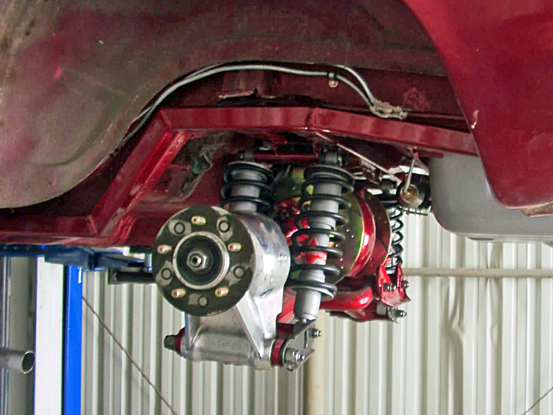
As quoted in your post irstang, "These slides, also, explain why motion ratio should be kept as close to 1:1 as possible, thereby reducing loads on the body." Also maximizing travel in the shock. Plus this setup mounts to the bearing carrier which gives app. 99% of the motion. The Corvette C4 with coil overs has something going for it!
C4 Corvette
I think the Corvette rear is a great choice! The one with the trans axle would be fun. One could improve the weight distribution to improve handling even more.
D2
Looks to me that D2 is the intersecting point of the center line of the damper and the center of the spindle mounts. On the IRS it would be the damper center line and the bone/half shaft u-joint center line.
What confuses me about the Jag IRS is the twin spring shock deal. How do you fine tune your suspension with twice as many parts. Also, one set in front of the axel and one set behind. Seems it would be hard to dial in.
Why would you not buy an after market coil over to make things a little less complicated? Other than $$$$$.
Money
It does come down to money. With 4 coilovers to buy it gets expensive in a hurry. It is difficult to tune the suspension without the benefit of ride height adjustable coilovers. It can get costly trying different springs, especially custom springs.
The two coilovers per side don't have to be perfect in rate and adjustment so it's not that difficult to tune, just expensive.
Some More Thoughts on Improving Motion Ratio
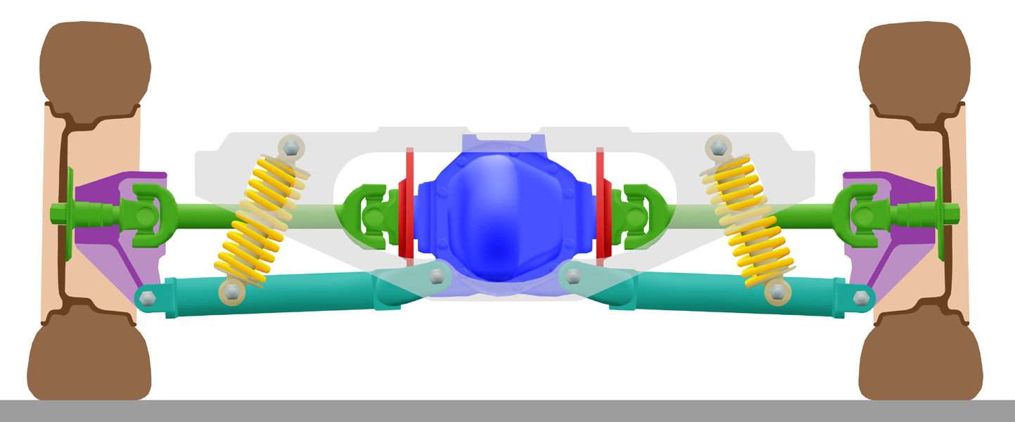
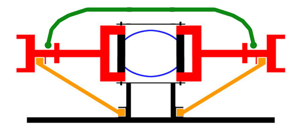
I borrowed this diagram from Wikipedia.Org. This looks like it is sitting about where Daze wants his A-arms to be at ride height.
Springs, I have learned from Daze in this diagram, are 1968 or earlier. Later models have a shorter spring but eye to eye distance of the shock is the same. I measured this distance on mine at 13.4. I wonder what could be done with the later model by machining different length spring collars to adjust ride height?
Daze gave me some numbers on his LCA's. They are 18.25 center to center and the coilover attachment is 12.375 out on the arm. His LCA ratio is .678. The LCA ratio before he shortened them 2.125 would have been .711. So shortening of the LCA did not make a big difference. What one has to be real careful of with JAG IRS is the coilover angle.. The ones in this diagram are somewhere around 20 degrees off vertical. This is the maximum I would want to go when we already have a marginal LCA ratio to start with. Angles down around 10 degrees are going to have very little effect. Cos10 degrees = .985 Motion ratio would be .668
Cos20 degree = .94, Motion ratio .637
Cos30 degrees= .866, Motion ratio .589
Cos 35 X .678 = .55 With this low of a ratio Spring rates have to be double the rate at the wheel. Loads on the body go way up when we start looking at high spring rates, even with the Jags two coilovers per side.
I would like to see some numbers from Daze with his shocks as vertical as his mock up will allow. Something around 15 degrees would be nice.
We need to keep the motion ratio as much above .6 as we can.
I am hoping to mock it up on Monday
I spent the better part of Thurs. and Fri. doing all the little stuff to my mounting bracket system. I enlarged the top 4 differential mounting holes in my cross bars to 1" so that I can insert and weld in a 1" sleeve with 1/4" walls so that the mount is solid for the purpose of torquing it down. I elongated all the holes in the 2" piece of steel that goes inside the front cross bar to triangulate it and box it in in the places that I had to trim for clearance purposes. I welded up 4 of the original shock mount holes I had made that will no longer be used, and then ground them smooth. I enlarged the 3/8" holes to 1/2" to except the upper shock mount bolts, finished notching and trimming the other side bar and removed the OEM spring stop from the passengers side. I am basically ready to tack weld it all together so I can do one last mock up and check the ride height. Should have the rest of the measurements you want when I do.
1 of 1