
 |
 |
 |
 |
 |
You are not logged in. Would you like to login?
 1 2 Jump to
![]() Offline
Offline

Mike looking at the quantity of work involved in the making, $40.00 for what you get seems cheap to me.
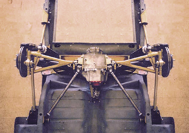
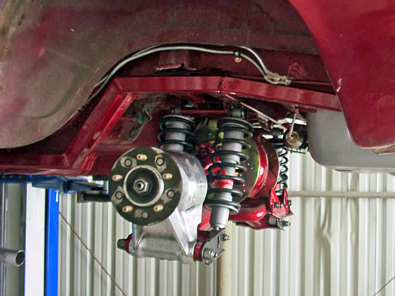
Here's another UCA made for clearance. Built for the Cobra IRS by Kenny Brown.
Last edited by Ralphy (6/25/2012 2:35 pm)
![]() Offline
Offline
Ralphy wrote:
Mike looking at the quantity of work involved in the making, $40.00 for what you get seems cheap to me.
Here's another UCA made for clearance. Built for the Cobra IRS by Kenny Brown.
I agree, I have tried to source the raw material, a 4.5" diameter x 1" thick alloy piece would be $15 each, not including shipping, in the annealed state.
If I had better or real machining center I'd seriously consider it, but right now, just a CNC Bridgeport and manual lathe. I'd have to hand tap those as well, which means for me, a few broken tapes and possibly a scrap part or 2 ![]()
For the UCA, with all the known working examples posted (such as above), I should just go that route
Holy moly....that has to be a misprint or they just like to milk the Cobra IRS crowd...$850 per pair? I'm all for someone making money, but at that price, they are insulting the customer in my humble opinion.
Last edited by Mike94531 (6/26/2012 3:07 pm)
![]() Offline
Offline

I'm sure Kenny Brown has done some testing and from his page it reads. "Significantly reduces weight and increases strength".
I've seen aluminum uprights going for $1,000.0 EACH! That's why I'm saying $40.00 equals cheap.
Ralphy
Last edited by Ralphy (6/26/2012 3:11 pm)
![]() Offline
Offline
Ralphy - we need to get you moonlighting building some custom uprights - or tyrrellracing - maybe Daze?
There is a profit deal in the making.
Cheers - Jim
![]() Offline
Offline

[img]*MYp3aPgjM82nbnoHezDXnNfhIL*IkdcTZDR8fB4iyuzOdaZ-DbS4UpKGMPkUXyOiXnFUHYrJfBb8/homer_simpson_doh_02.gif[/img]
I just see everyone wanting something different for starters. Then liabilities if you started to sell.
Last edited by Ralphy (6/27/2012 5:59 am)
![]() Offline
Offline
phantomjock wrote:
Here is an internal link to the loads analysis:
Not quite 60/40...
UCA 47%
53% LCA
Cheers - Jim
In this months edition of Racecar Engineering, a question about the loads on the UCA and LCA for the front suspension are asked in the Technology Consultant section answered by Mark Ortiz.
50% was his answer. No math shown, will have to go buy it to get more specifics, unless someone reads this post and can add more info or wants to head on down to the bookstore and read the article themselves.
![]() Offline
Offline
Ralphy wrote:
I just see everyone wanting something different for starters. Then liabilities if you started to sell.
Ralphy - Have you read the - hold harmless clauses on just "books?"
E.G., "...Racing and driving is inherently dangerous, blah, blah, blah..."
An LLC and a LIABILITY insurance rider - for refund or replacement only might be a way to go.
The litigious nature of today's society has closed many a small business - before it even opened! Not a political/religious/etc statement - just an observation of a small business owner - that now does mostly design work and not manufacturing.
Mike94531:
As to the 50 percent - I say not true. If Mark Ortiz can support - I wish he had. He is highly respected, and his Chassis Newsletters are renowned (I have many of them) - but he should provide some support to that claim. (Makes me wonder, if there there was no data or analytical support, is it opinion and not fact based? Boles has been accused of similar less than factual assumptions in print - so we are all fallible.)
I make no claim to the maths I provided earlier - just they seem rational and offer some engineering proof. Perhaps his comment was offhand - and not intended to be fact based - can't say, haven't read the article.
Let's try an example - put the vehicle in a turn. Look at the IRS (we are concerned with IRS - Mark's comments were specific to IFS - and I won't address that here.).
The primary load in a turn is transferred at the surface with the contact patch. As the load migrates through the deformation of the tire, to the wheel, then the spindle, then to the Upright, and then to the LCA/UCA. The majority of the load on the LCA will be in tension on the (inside) loaded tire/wheel/suspension, and compression on the outside. BUT, the outside wheel actually "unloads" in most designs and has less force in it's LCA.
The UCAs are doing their thing (authentic-throw-back-hippie -engineer-talk), and that they "showed up for work" get 50 percent of the credit -- but not for carrying 50 percent of the load. [Kinda like the slackers you see at work sometimes.] -- observation - not political!
The inside wheel LCA is in tension, and is taking the majority of the load from the UCA that is in compression. Any wonder you see Larger-Beefier LCAs and wimpy UCAs - except as previously noted, ease of manufacturing?
The design challenge for the UCA is to keep it from buckling under compression, while having enough tensile strength for the anticipated loads. Shape design can be very helpful - but not germane to this discussion.
RANT - Over.
When I find a copy of Race Car Engineering I'll gladly review it -- not too popular here on the Red-Neck-Riviera. Any copies/transcripts greatly appreciated.
Cheers - Jim
BTW - I'm sure I have a graphic somewhere to save all the reading, after all, 1 jpg = 1K.doc! ![]()
![]() Offline
Offline
Phantomjock: you are right I was thinking camber and typed caster. I didnt even notice it on my proof read until much later when your post pointed it out. As for all the cool IRS images. I have seen what those curved control arms flex in a heavy state of lateral load. I realize this is directly proportional to vehicle weight so it is highly unlikely a 2500 lb cobra is going to flex the UCA like my 3500lb mustang would when both cars are going around the same corner at the same speed. I am also aware this flex can be overcome to a realistic extent with the use of heavier wall tubing but then you wind up making the arm with greater mass and increasing unsprung weight. The only route I think I would take is by utilizing chromally tube of relatively thin .09375 wall but approximately 1 3/4 inch in diameter for the curved UCA idea. For cars weighing 2500lbs or less suspensions in the images posted should perform as well as the alignment will allow it to.
Again. those images of IRS's look like they were built by skilled fabricators and are pretty damn cool!
![]() Offline
Offline

Barnes & Noble sells it , I just leafed through two different months last week. And just changing the axle CL relative to the UCA and LCA would change the load ratio alone no?
Ralphy
Last edited by Ralphy (7/02/2012 8:26 pm)
![]() Offline
Offline
Yes Ralphy I too believe the location of the axle center line on the upright should dictate the percentage of load on the control arms. Phantomjock is also right in a way because the vast majority of uprights have the axle C/L closer to the lower control arm and due to this the LCA in those applications will have the greater lateral load . Even front spindles usually have the axle C/L much closer to the lower ball joint. Drop spindles are almost an exception however I have yet to see one built with the axle above center. Weather its a front spindle or a rear upright, moving the axle center line too far up would drag the lower control arm on the tarmac or at the very least put it in harms way.
![]() Offline
Offline
Guys -
My Bad - I thought the loads discussion was in this thread - and didn't check.
Here is the internal link and a link to the research paper:
There is no indication in their analysis that the relationship of distance from the spindle centerline (CL) and the Half-Shaft CL affects the loads - but as tyrrellracing points out - it seems quite intuitive.
For my layout - getting quite far afield from this thread - but anyway - I am focusing on getting the LCA Upright mount as close to the lowest position of the wheel rim as possible. This was a bit I picked up from reading Staniforth I recall.
Cheers - Jim
![]() Offline
Offline
Phantomjock: The three dimensional summation of forces you posted are a good place to start for analyzing suspension design in general. However as I am sure you know those equations were for static measurements. Things dont get exciting until they become dynamic. No one would care much for cars if they remained stationary. I was talking to my brother the other day and he reminded me that the loads fed into suspensions are normally fairly light. Its the spike loads we should be concerned with. they are what break things in a hurry. If our tax money went to infer structure instead of feeding and supporting illegals migrating from other country's we might have good enough roads that we could reduce the factor of safety in our suspensions. LMAO Until then we must build heavy duty suspensions just to safely make it to the corner market.
Most of the summations I have seen on line have basically disregarded the axle's location on the upright or spindle. Since this is nearly the loads origin in its path to the frame, the math doesn't really produce the information I was after. Or perhaps another way of looking at it would be to accept a factor of error built into the results.
This is in no way an insult rather its just my opinion.
Ralphy: did you have a link to the $ 1K uprights? I was hoping to see what one grand worth of upright looked like. Or if it was priced so high to cover legal expenses if the maker gets sued and has to defend himself against a frivolous law suit.
![]() Offline
Offline
I guess it has been a while since I've been here...not too much progress on my end ![]()


![]() Offline
Offline
I have a 2004 volvo v70 its front wheel drive i want to know if the rear subframe and it's from the awd or cross country will bolt in? I can't find any pictures for comparisons! And help would be appreciated!
Last edited by HerbiefHall (12/27/2016 6:15 pm)
 1 2 Jump to