
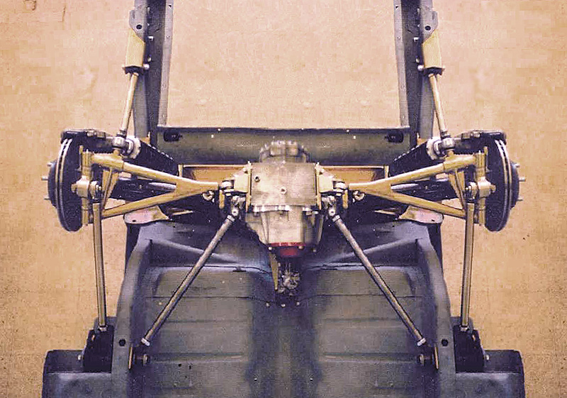
 |
 |
 |
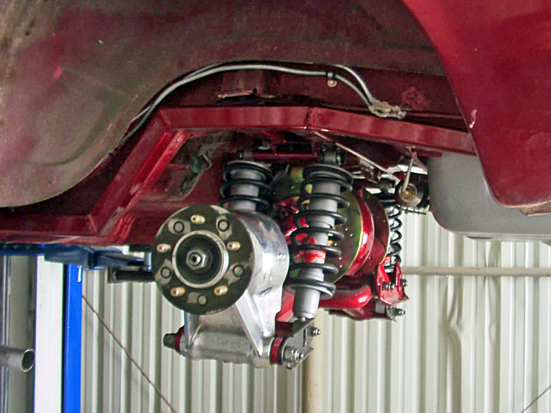 |
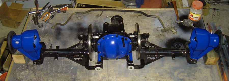 |
You are not logged in. Would you like to login?
 1 2 Jump to
![]() Offline
Offline
Greetings all.
I am in the process of putting an IRS under my '78 Volvo 242.
So far, I've just taken everything apart to clean and paint. I hope to be sandblasting the center section and rebuilding the Traction-LOK this weekend (went with the carbon discs)
Anyway, as usual, this is one of those projects that I took on without doing enough homework before buying parts.
My questions that I did do a little searching but couldn't find any concrete answers to:
Axles......... 4" too long, I found the company that makes them Factory Five, however $500 is too much $$$ right now. I've already cut 4" from each axle with my plasma cutter, now I'm looking at building up the OD by welding and cut new splines.
The outer uprights.........I want to flip them to gain more room since I'd have to copy the Ford design with a bent upper arm like they used.
The only Ford parts I have and plan to use so far is the center section, the uprights, the axles (modified) and hubs (which I need to modify to a 5x4.5 pattern to match my Ford Mustang Cobra rims)
Thanks.
Mike in Antioch, CA
![]() Offline
Offline

Mike welcome aboard. We all would love to see some pics when you have time. Below are a couple of links. The first is a Factory Five owners site. Not Factory Five Racing. You also might try Club Cobra which includes all makes of Cobras plus some. I would try the search feature and or become a member and ask. Another possibility is to ask at Denny's Drive Shafts.
Good Luck,
Ralphy
The wife is an S70 owner, good car!
Last edited by Ralphy (6/16/2012 5:53 pm)
![]() Offline
Offline
From my experience cutting down a half shaft welding up the diameter of the cut end then cutting splines in the weld is a bad idea. If that was what you were planning then taking a 4 inch segment out of the center of each shaft then weld them together with tubing similar to how Daze did it would be better. You will not get the right metallurgy to cut splines that will last from weld. I have seen the weld and respline trick fail too many times.
![]() Offline
Offline
Thanks for the reply's..
Well, I've already cut the axles ![]()
I picked up some RG60 gas welding rod today, I think I'll give it shot, I'm hoping worse to happen is the splines fail and just spin inside the CV or Trilobe ![]()
I've also toyed with cutting off the CV and Trilobe and welding on a flange so that I can use Porsche CV joints, new custom axles can be had for less than $250 a pair.
Car is not that heavy and right now it'll be around 150hp for awhile till I figure out what I really want for motorvation .
![]() Offline
Offline
Missed the 3 posts before picture rule..
![]() Offline
Offline
So far pics are boring. Feel free to make fun of my pic as long as you have "something" constructive to say, hahaha
Panhard bar mounts removed

Samples cut off to be sent to have tested by a metallurgy lab
Slowly drawing up the parts in Alibre CAD/CAM, this is from MOI, another 3D software. I traced the factory drawings to create the factory rear subframe.
Suspension fresh from the Fairfield Pick and Pull
Uprights, one has been sandblasted in my cabinet.
Case getting ready to be blasted and painted.
Tri-lobe, 930 Porsche CV and stock T-bird CV with t-bird axle below.
Getting ready to remove the CV off the axle
Last edited by Mike94531 (6/19/2012 1:14 pm)
![]() Offline
Offline

Making fun? I don't know about that. But I am jealous in the fact you have those CV axles. Something I like about your setups design. Your LCA is very high, being close to the axle centerline at the upright. That alone makes for a stiffer design. You should get little twisting at the upright. My C3 has app. a 6" spacing.
Also I'm guessing you have seen others with your Lincoln IRS build a LCA that is lowered at the upright to gain coilover length? If you flip your uprights, where will the coilovers mount? Saw another guy Ant at Club Cobra attempt the same and he gave up.
Are you going to remove any nicks and polish the housing?
Ants Pics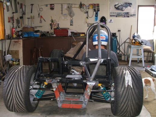

Ralphy
Last edited by Ralphy (6/19/2012 5:57 pm)
![]() Offline
Offline
Wouldnt the longer control arms on top give you a positive camber gain? Negative camber gain will normally provide the best results.
Or am I missing something....
The suspension in your images would gain positive camber with the outside tire in a corner which would be detrimental to the lateral grip especially with wide tires.
Can you show rear view images at full droop, ride height, and fully compressed?
I admit that I fail to see any benefit flipping the uprights could have to the geometry as a whole. Once flipped the pivot points on the upright would all be in the wrong locations geometry wise and moving the frame mounts to provide a more geometry friendly length control arms would probably gain very little. The camber curve would be backwards, the king pin axis would fall completely away from the tread patch. Even if the tire doesn't turn this axis plays a role.
Where is the gain over the original orientation? If you are trying to make it into a drop spindle type upright, fabricate an upright with the axle center line where you want it. Just flipping the upright will gain you a tuning night mare and little else.
Last edited by tyrellracing (6/19/2012 6:59 pm)
![]() Offline
Offline

TR looking at Ants pics I was saying the same thing in my mind back months ago. However, if your building yourself you can make your arms any length. Ants arms sure miss the 2/3rds formula.
I keep looking at these pics and can't tell which really is longer. The lower may be a bit longer. He should get some camber being the lower appears to still be moving outward and the upper being level. I've also seen pics/builds with the uprights in the proper position with fairly even uppers and lowers. I'm not sure of the reasoning.
Ralphy
Last edited by Ralphy (6/19/2012 7:30 pm)
![]() Offline
Offline

Here's another point, Ant put his coilovers to the rear. Placement has been something I kept questioning, in front or back of the halfshaft? IMO from what I have seen, if you haven't a true UCA the coilover goes to the rear. Why? With the acceleration forces at the hub, with no upper control. The tendency is having the axle to want to walk over in front of the lower control arm. Placing the load behind counter reacts this twisting, the harder you accelerate the grater the load on the coilover.
Then with a true double wishbone the upright is pinned in place top and bottom. Assuming the UCA stays solidly located, the acceleration loading will now cause the exact opposite condition on the lower control arm. It will twist up to the front. So now it may be advantages to put the coilover in front. Ant has his to the rear.
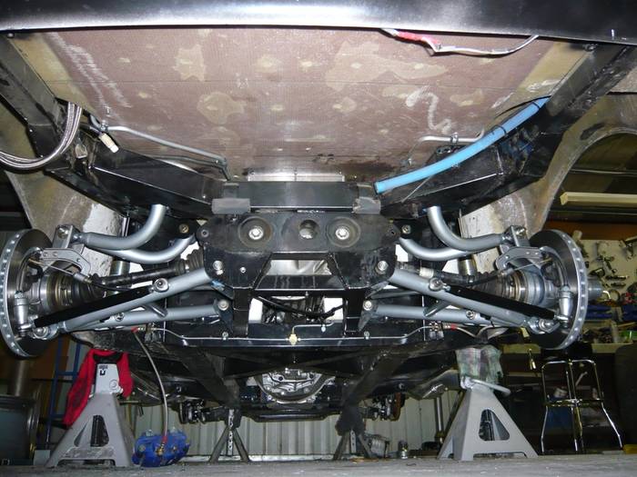
Check this pic out, do you see the wear marks on the halfshafts? He has the coilovers on the wrong side. The LCA's are being twisted. If you blow the pic up, you can see what may be a line on the right HS also.
Last edited by Ralphy (6/19/2012 7:10 pm)
![]() Offline
Offline
Ralphy, Didnt you say that someone in the cobra forum tried this idea and in the end wound up abandoning the concept? I can only guess the desired result would be to lower the suspension in relation to the wheel center line height.
I still think the best way to gain these results would be to fabricate custom uprights.
As for the coil over locations, I agree 100% with your reasoning and the image proves your point clearly. I have never liked the ladder type design LCA with out a conventional upper control arm to support the torsional loading.
Last edited by tyrellracing (6/19/2012 7:16 pm)
![]() Offline
Offline

Yes, the pics I posted are Ants pics and he gave up on the idea. I agree I just saw a pic of a car with a notched frame and reinforced at that point.
If you do have a true double wishbone, my thinking is front/back is not as big of an issue but front is the favorable place.
Last edited by Ralphy (6/19/2012 7:32 pm)
![]() Offline
Offline
Mike 94531, you are right. when the splines failed they simply sheared off leaving the original shaft in the cv's inner bearing race. The end result was like shifting into neutral. No harm to any parts beyond the twisted in half CV boot. If you pull it off you will have succeeded at a discipline many have failed at including my self. Mine lasted about two weeks of street driving until I tried to launch. No noise, just like popping out of gear.
![]() Offline
Offline

Oh the advantages of having an UCA. Can't imagine the damage I would have with the C3 design.
![]() Offline
Offline
One more thing for mike 94531
The Porshe and Volks CV joints are all to them selfs in the world of CV's. The joints are unique because they can plunge at both ends and by design are much stronger than others of equal size. I have had very good results with all the German designed CV's I have abused. Because of their reputation for being tough they have enormous aftermarket support and are reasonably priced. If you can fabricate the adapters to use them, by all means do.
![]() Offline
Offline
Yea I regret having no room to have put an IRS with UCA's in my Shelby. Using the half shaft as a stressed member in the suspension is kind of risky. Adding more than four times the HP the suspension was designed to tolerate is like pouring gas on the fire. To make matters worse I am saving up for the 6.125 H beam eagle rods I need to finish my 408 Fontana engine. I cant help but think that maybe I should start over with a different car and leave the Shelby with the power plant it has before I twist it in half.
![]() Offline
Offline
Glad to know someone else has flipped the upright, bummer it didn't work out for him. I have not drawn it up yet to see how goofy the motion is yet,
The reason for wanting to flip it is that I will have to run a top UCA with a bend in it just like the Thunderbird unless I notch my frame rail. It has a good 3" "dip" to it.
This is the Ford T-bird setup I found online.
Last edited by Mike94531 (6/19/2012 9:55 pm)
![]() Offline
Offline

That's not bad however two inner points are better than one.
How's this look, getting closer?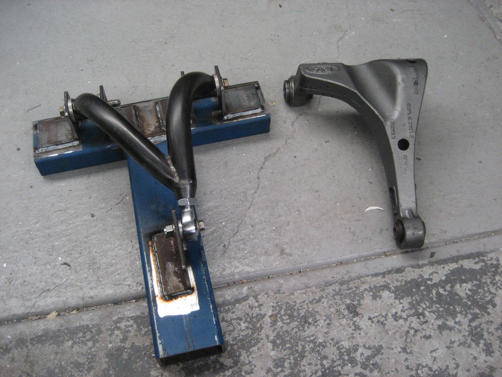
Or maybe this.
Don't let a bend scare you any. Look at this GM control arm.
Here's one with minimum clearance
Ralphy
Last edited by Ralphy (6/19/2012 10:58 pm)
![]() Offline
Offline
Ralphy - any more info on the last one? Link etc? Quite "industrial" -- yet functional in a funky kinda way. Cheers - Jim
![]() Offline
Offline

Hurricane Cobra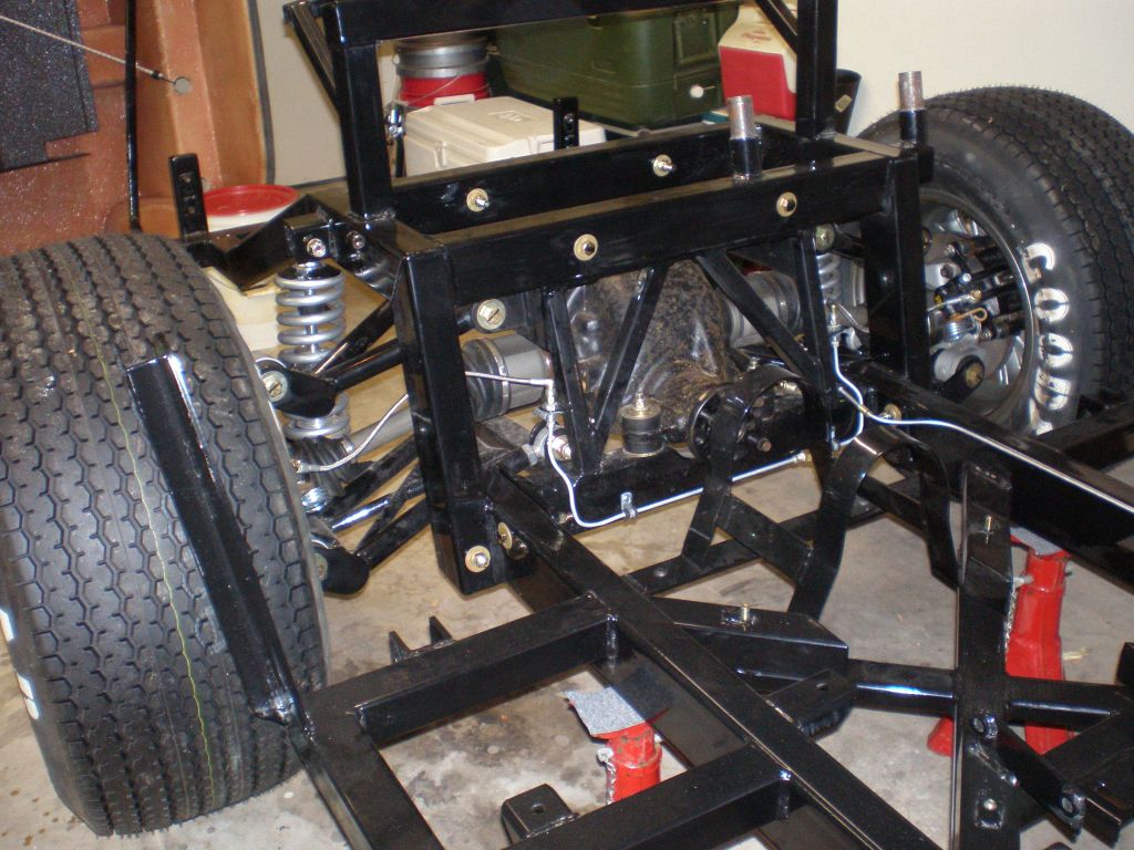
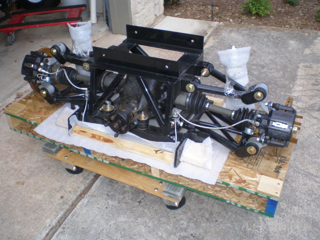
Mike,
The factory configuration you posted only provides support, removing the halfshaft as a loaded member. Offering little fore and aft control. With that design it's best to keep the load/spring behind the halfshaft. Adding HP I believe adding a true UCA is very beneficial. Also allowing the chassis load/spring to be moved to the front of the IRS HS.
Ralphy
Last edited by Ralphy (6/20/2012 7:21 am)
![]() Offline
Offline
tyrellracing wrote:
From my experience cutting down a half shaft welding up the diameter of the cut end then cutting splines in the weld is a bad idea. If that was what you were planning then taking a 4 inch segment out of the center of each shaft then weld them together with tubing similar to how Daze did it would be better. You will not get the right metallurgy to cut splines that will last from weld. I have seen the weld and respline trick fail too many times.
I'm getting another set of axles , so I think I'll try the cut-n-middle-n-weld method as well...
I found a few videos that show the process...add to video link page?
![]() Offline
Offline
I see the merit in the idea of flipping the upright. I just dont like the geometry it provides. I am in the same boat as far as no room for an upper control arm with out notching the frame rail. In my case that tends to break the unit body's back. The rear frame rails on old mustangs are weak and are notorious for cracking just above the rear axle so cutting them is out of the question. I have never been too fond of the "U" shaped UCA due to flexing. Fabricating uprights to achieve the clearance required while maintaining the correct geometry seems to be the way to go. At least for me. I doubt I would use 4140 for the bearing bore again. its just to big a pain to anneal and stress relieve after welding. Even then the bores relaxed after machining and went out of round by nearly .001. Realistically going from .0015 to .0025 press fit with mild steel should provide the bearing stability I want plus it is more stable than 4140 after welding.
BTW... Ralphy. Great pic's of the ford type IRS's food for thought
![]() Offline
Offline

My first thought is that when you corner that's when you would get the highest push on the UCA. But when you follow it through, don't the lateral G's go into the LCA pushing inward. Then actually pull on the UCA? In essence removing load off the UCA? The biggest loading would be when you hit a hard bump in a straight line. Add to this the upper is typically shorter which makes it more rigid than the lower.
Also the inherent design of the T Bird/Lincoln has the UCA well above the axle. This is the issue why so many have clearance issues to begin with. But this height actually may help to remove loading lbs. on the UCA anyhow? Where are our two resident engineers?
Ralphy
Last edited by Ralphy (6/20/2012 10:48 pm)
![]() Offline
Offline
As I understand it when in a steady state of lateral load, like a skid pad. The out side tire has its contact patch pushed toward the center line of the vehicle. This takes up all the free play and suspension parts begin to deflect under this load. The load path from the tire to the wheel will attempt to produce positive caster while the suspension resists this through strength of design. Since the forces applied to the wheel are in a manor that would create positive caster, the UCA would be under tension and the LCA would be under compression. The UCA might have no load for as long as .00001 second between compression and tension at corner entry but after that it should remain in a constant state of tension directly proportional to the cornering load until corner exit. These forces are roughly as significant as the weight of the vehicle times the "G" force generated. Another benefit of a SLA suspension is you can separate the UCA and the LCA further than would be possible with say a Jag IRS. This reduces the stress on the control arms and their anchorages.
I am well aware this was a readers digest version but I think I got my point across.
Last edited by tyrellracing (6/20/2012 11:32 pm)
![]() Offline
Offline
tyrellracing wrote:
I see the merit in the idea of flipping the upright. I just dont like the geometry it provides. I am in the same boat as far as no room for an upper control arm with out notching the frame rail. In my case that tends to break the unit body's back. The rear frame rails on old mustangs are weak and are notorious for cracking just above the rear axle so cutting them is out of the question. I have never been too fond of the "U" shaped UCA due to flexing. Fabricating uprights to achieve the clearance required while maintaining the correct geometry seems to be the way to go. At least for me. I doubt I would use 4140 for the bearing bore again. its just to big a pain to anneal and stress relieve after welding. Even then the bores relaxed after machining and went out of round by nearly .001. Realistically going from .0015 to .0025 press fit with mild steel should provide the bearing stability I want plus it is more stable than 4140 after welding.
BTW... Ralphy. Great pic's of the ford type IRS's food for thought
Well, I think I have been inspired to figure out how to "raise" the boxed frame rail, I'll know more once I remove all the parts I have stored in the trunk and take a look at the floor from inside.
What inspired me?
Seeing the JBL Cobra build ![]()
![]() Offline
Offline
tyrellracing -- Concurr.
Except I believe it is forcing positive CAMBER...
The load path from the tire to the wheel will attempt to produce positive caster while the suspension resists this through strength of design.
The reason Chevy and others have gotten away with using the halfshaft as loaded members - the majority of the load is through the LCA.
I haven't done a loads analysis (or literature search) on it - but expect its more 60/40 or 70/30 LCA/UCA. And as tyrellracing pointed out the loads are in tension. I suspect the reason we see LCAs and UCAs built the same size materials - simply a matter of fabrication convienence and little gain by downsizing the UCA even from a unsprung weight advantage.
Cheers - Jim
Last edited by phantomjock (6/21/2012 6:01 am)
![]() Offline
Offline

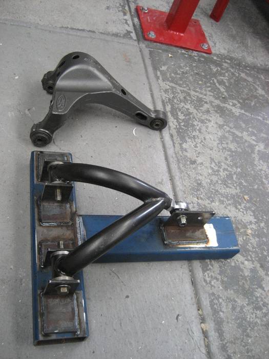
For a visual I posted a pic of the upper TR mentions. I think anyone with any reasonable understanding must look at the upper control link and wonder if it's strong enough, I know I do. Also my thinking is if you upgrade to a true double wishbone strength no longer becomes an issue. If that single bent tube can get it done? A arced wishbone/A arm should be fine.
Jim, I think were on the same page, yes both are in tension but the lateral forces do reduce the amount on the UCA when cornering. The LCA is the true workhorse on an IRS.
You would think a company such as Heidts would have done some analysis on their components. However did they find this adequate with some flexing or is it plenty rigid period.
I think Chevy and other manufactures also got away with using the HS as a member is liability.
Surely this has more merit than the Heidts above.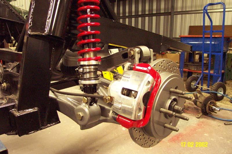
I know I repeat this over and over but notice how the coilover was moved forward with a true UCA.
Name That Part
Ralphy
Last edited by Ralphy (6/21/2012 7:32 am)
![]() Offline
Offline

Here's some more pics thanks to Aussie Mike at CC.
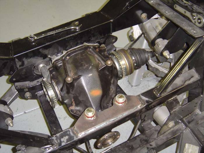
This appears to not be his car or the same as above that is.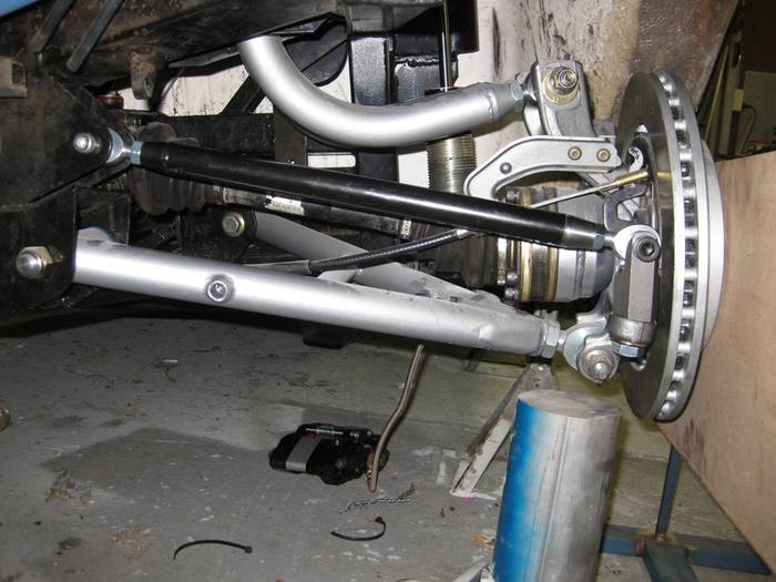
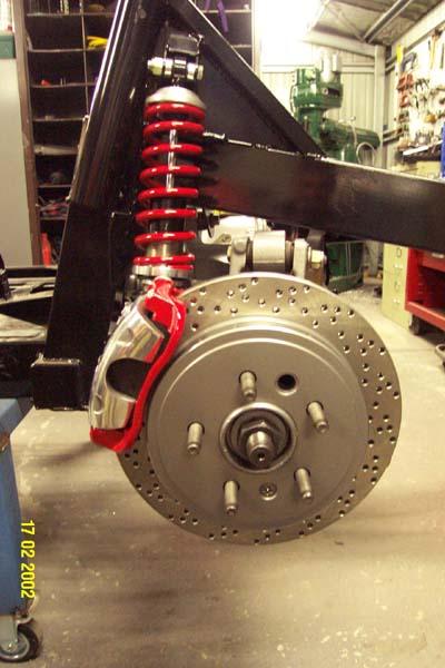
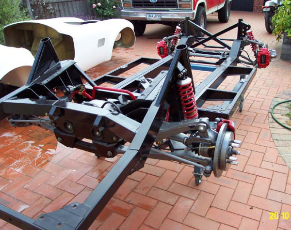
Ralphy
Last edited by Ralphy (6/21/2012 8:00 am)
![]() Offline
Offline
Back to the axles....
I decided to go the 930 CV route (or attempt to) after talking with a guy that has successfully done the mating of 930 CV flange to stock stub axles, his applications are for serious off road 4x4's that put a tremendous amount of torque and twisting action on these parts.
chromoly flanges, $40 each..a little pricey, so I might just order one pair and once I get them see if something I want to make for the other axle. 
![]() Offline
Offline
Here is an internal link to the loads analysis:
Not quite 60/40...
UCA 47%
53% LCA
Cheers - Jim
Last edited by phantomjock (6/23/2012 2:55 am)
 1 2 Jump to