
 |
 |
 |
 |
 |
You are not logged in. Would you like to login?
![]() Offline
Offline
First off. What is Motion Ratio and why is it important? Motion ratio is defined as the change in spring travel divided by the change in wheel travel. MR= delta ST/ delta WT
Motion ratio is important to calculate a spring rate in order to achieve a desired wheel rate. Or the opposite; one may wish to know what wheel rate to expect from a set of springs that came from a donor car. There are other important effects, but more on these, later.
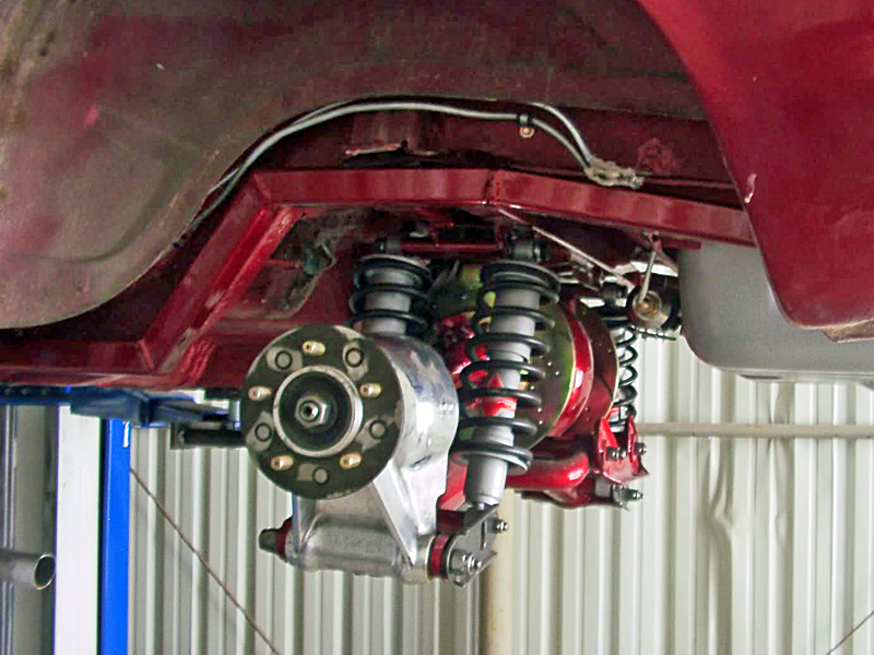
When one first attempts to determine MR using trigonometry for the canted spring, and ratios of spring positions to the length of the lower control arms, the math gets unnecessarily cumbersome. As installation in my '65 Mustang convertible progressed I found an easier way. Remove the coil-overs and substitute a set of straps, top hole to the cross member attachment, with an additional three holes an inch above ride height, at ride height, and an inch below ride height. The straps become a handy tool for supporting the suspension while you measure the resultant changes in wheel travel. It is simple to measure a wheel deflection at the tire patch or spindle. MR becomes a simple division problem.
So once we know the motion ratio, how do we calculate spring rate for a particular wheel rate? It is real easy with canted springs and shortened LCA's to have a relatively poor motion ratio of around 0.6. Let's use a relatively light 150 lbs/in wheel rate to show what happens. It is easy to see that for every inch of wheel travel, the spring must support a load of 150/MR = 150/0.6 = 250lbs. Watch out. That is a spring rate of 250 lbs per 0.6 inches. Springs, however, are rated in pounds per inch, so you have to divide the 250, again, by 0.6. This is why the formula for determining spring rate becomes Spring Rate=Wheel Rate/MR x MR or MR squared. In this example the spring rate would be 416 lbs/in. A lot of spring for such a light wheel rate.
Take a look at the following reference to see what happens with a MR of 0.5.. I know it is cited somewhere else in the forum, but here it is again: Steve Lyman's Suspension 101, as a PDF file.
Motion ratio, spring rates and wheel rates become real issues when the Jag IRS resides in a significantly heavier or lighter car. Modifications such as shortening LCA's and canting coil-overs have negative effects on MR ratio. As motion ratio decreases, spring loads to the body increase. High spring load force is felt by driver and passengers as the wheel is upset by a change in road surface. And, to make matters worse, shock absorbers don't work well with small changes in stroke.
The standard practice of shortening Jag LCA's is to make the cut all from the inboard side. The wrong side to improve MR. Anybody have some ideas about how to move the coil-over attachment bosses outboard? I know control arm/radius rod attachment would have to be done in a different way.
Last edited by irstang (9/13/2015 11:49 pm)
![]() Offline
Offline
irstang -
Great intro and some solid point there. What I think is needed is something that puts the "so what' in place.
I'll try this:
"Shocks depend on velocity to do their job - if they are not moving, they are not displacing fluid, which means they aren't doing anything. The more shock travel we can get per unit of wheel travel, the better we can control every microscopic bit of that wheel travel. This also allows us to control things with lower shock forces, which makes it easier to find reasonably priced units.
In an autocross car with a good motion ratio, we're generally looking for what the shock does at about 3 inches/second on a force vs. velocity graph (explained somewhat here: ). Most of the movements the suspension sees on an autocross course are in this speed range, so that's where we care about what our shocks are doing. Shock velocities above that speed (bumps) are important too but somewhat less so,..."
Now, I shamelessly borrowed that from a discussion on Camaros and autocross over at :
He gives a quick summary that is like this:
Bad motion ratio gives shocks poor control of sprung/unsprung motion
Bad Motion Ratio leads to inconsistent tire loading.
Bad Motion Ratio creates a lot of suspension travel at "normal" spring rates.
Bad Motion Ratio exacerbates the problems with the suspension's camber and bumpsteer curves.
Hope that helps put a bit of "why should I care" to your good points.
Thanks for bring those up!
Cheers - Jim
![]() Offline
Offline
IRSStang, I tried to go to your link (SAE org) but it looks shorten and I'm getting a 404/Page not found error.
Can you try posting again?
Thanks!
![]() Offline
Offline

Jim,
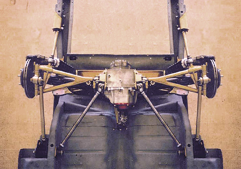
Thanks for the input and kind words. Intuitively I knew the Jag IRS motion ratio was something to be careful with. Your comments really help drive the point home. I "shamelessly borrowed" the picture below from the internet. When I see a motion ratio like this, probably less than 0.5, it makes me cringe. If the intent was to run only one shock, why not have a mounting boss on the opposite side of where a radius rod should be? There is plenty of room to move the coil-over outboard on the upper crossmember. Maybe Daze has some ideas, because this would improve the MR, and handling, for a lot of guys out there that want to shorten a Jag lower control arm.
Regards,
Douglas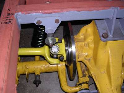
![]() Offline
Offline

Some great posts guys!
Ralphy
![]() Offline
Offline

Hi 303Radar,
The one thing I did not proof was the link. I believe it will work now. Why it worked over in the roll axis thread and not here is beyond me.
![]() Offline
Offline

Some good points, and I especially like the idea of moving the shock outboard. Could anyone comment on the convention of pointing the shock towards the tire contact patch? Intuitively it seems good, but in looking at leverage, ratios and all that it seems it shouldn't matter in the least. Especially in light of some of the cantilevered inboard designs.
Seems pretty obvious that up to the design limits of the shock, the more shock motion you can get for a given wheel motion the more tunable the suspension will become. So wouldn't the first requirement be to determine the limits of the shock? We have some pretty advanced off-road units, but why would we want to use that here? Seems like size and complexity is an issue. The key I think is to work within the performance envelope of the shock or coil-over that fits the available space at a reasonable price.
Jim
![]() Offline
Offline
Great info, Stang ! ! !
So, to get specific, what IS the nominal spring rate for a quad spring/shock combo for an XKS ? By the way, with your guidance and Daze's postings, I'm going to try to locate a driveshaft/machine shop in the Austin area this week to cut down my Jag IRS. This afternoon, I mounted my tires and took "final" measurements to get the wheel/tires to fit under the '49. It looks like I'll be cutting out about 4" from each side... ... I surely like the idea of moving the shock mounts out as far as possible. By the way, does anybody have any idea of nominal ass end weight of a '49 Ford Coupe? Will take a shot at the math as you've posted it..
And thanks .......
![]() Offline
Offline

Hi '49.
Wow. Sounds like you would like to try some new ideas. As far as spring rates for an XKS. are you sure the donor car was not an XJS? I could not find any spring rate info on any Jag coil overs other than the OEM parts that Daze measured at 200 lbs/in, each. I did find that a stock '49 Ford Coupe had a curb weight of 3100 to 3200 pounds. A Jag XJS weighs 3900-4000 lbs. Is there a way as your build progresses to get accurate corner weights for your car? It will be interesting to see with your change in motion ratio whether or not the springs you have will work.
Best Regards..........
![]() Offline
Offline
Well, hell, between my dwindling synapses and constant changing of attention to various subjects and women, I don't know WHAT the damned thing came out of... here is what I have: a casting number in the bottom of the diff. says : "C04HU004037", then below that is "+CF+L", the tag says "2.88" (there is only one tag).
Here is what I posted a few days ago..."Oh, and the tag (there is only one) indicates 2.88 ratio.. there is a stamping in the machined surface next to the cover the appears to be an "L" above an "E" and what looks like "2" and "5". There is also an "86" above the "2" and "5"... so I guess it's an '86 ???? The flange to flange dimension is 61" (or 60.75?)"
By the way, since the XKE is much narrower, I wonder what spring rates and swing arm lengths and shock mount dimensions are? Could somebody do a little ExCel spread sheet with those lengths and dimensions and motion ratios there are for all the Jag configurations? along with identification numbers?
If they exist here or elsewhere, I've never seen them (that I remember..ahahah)..
The LCA's are 20.5" between pivot points and the shock mount is 14.5" out from the inside pivot...
After measuring with the "real" tires in place, my initial calc's seem to indicate that I'll need to cut down the width by a minimum of 3.25" each side. Now, I "could" modify the wheels to either move the center section out by 2" or reverse them for the same dimension. But that would just make the "gettin' the tires off and out from under that dang wheel well" situation even worse.. hmmmmm
The total width to the outside of the tires is 73", and the inside is 51.75". Wheel well inside width is 67.5". If I allow 1/2" clearance, then the "cutdown" needs to be 6.5", or 3.25" on each side...
Thanks for all your attention and help, Stang. Wonder where everybody else is ???
Paul
![]() Offline
Offline

Paul,
I think everyone is still with us. We are all in a little bit of shock over the loss of Carroll Shelby. Mr. Blackwood has a good question on why do we cant the springs at all. Hopefully we'll get someone to chime in on that question. For the purpose of Motion Ratio it is important to keep the springs canted less than 25 degrees off vertical. That keeps the spring angle correction factor greater than 0.9.
All XJS rears were 61 3/4 inches wide with the early versions having a 3.31 ratio and the later cars a 2.88. Are you measuring flange to flange with the half-shafts straight out? In any case, you are right to shorten the LCA's the minimum amount necessary.
Anyone have some dimensions of an XKE LCA?
Regards,
Douglas
Last edited by irstang (5/15/2012 10:58 pm)
![]() Offline
Offline
Hey, guys, I just noticed something..
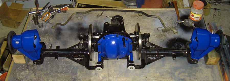
It appears that a person can/could narrow the cage by a maximum of 3.5" on each side and still use the mounting configuration as Jag designed it without disturbing ANYTHING relative to the hardware except the ends of the cage. It surely would be easy to carefully cut out between the shock mount and the "reinforced end plate", move it in, and reweld it (with a little more support, with a couple of plates). I'm not "HOT" on building/buying/modifying anymore than I have to just so that when/if anybody sticks their head under my rear bumper has some sort of orgasm over how beautiful/lovely my rear end is. It's going to be rather low anyway... so this morning I was getting ready to pull the other axle and I noticed that there is some "meat" to the outside of the cage shock mount.
[img][img/]
And I surely don't know why, but I've not seen a smidgen of any pictures or discussion about using the cage rather than "start all over" with mounting...
What do ya'll think?
![]() Offline
Offline
well, crap try this then..
Do you HAVE to use the "imageshack" thing or what?
![]() Offline
Offline
Oh, hell, never mind. I am NOT drunk.... the above pose is BS..... for narrowing the cage, one would cut INSIDE the shock mounts to keep the geometry "approximately" the same, not outside the shock mount...and there is plenty of room to cut the cage there...
So the question sorta still stands.. "what is wrong with narrowing the cage" ??????
![]() Offline
Offline
hmmmmmmm.... wonder where my avatar went ?
![]() Offline
Offline
Testing a feature of putting images here....
![]() Offline
Offline
Stang - thanks for the updated link!