
 |
 |
 |
 |
 |
You are not logged in. Would you like to login?
![]() Offline
Offline

You never stop do you TR? I think if you look back I have never criticized you until you start the jabs. This thread in example. Go find where I said anything about you.
Next you have stated your going to post your pictures. The last time you did it was never asked by anyone here including me. Your explanations are good but pics can really tell the story. You seem to have all the facts about the AC Cobra and the Ford 427 you have posted. You never built or owned one of those so what gives you the right to have an opinion about either or? You argued about the 427 SC not having roll steer did you build one? I was right it does. You also went on how the 427 SC had leaf springs on the IRS? Again I showed you you were wrong yet you kept up the attacks. Again, you never built one did you. You said the Ford 427 was a truck motor again you kicked and screamed. You never owned one and you had an opinion. So why should you have any opinion. However I showed you. When I state something I look for facts and then post them here to validate what I have said. You state things and never post any pics or links to validate your point. But TR I listen anyhow and try to understand. Do you know how to copy and paste? Do you know how to show an image here? Because my thinking back, I can't remember you ever doing either. Now I'm not trying to beat you down but if you can't me or others can show you how.
Bottom line: My critique of Ralphy has always followed his criticism or down right accusations of me.
Why would any one want to download images of anything they built only to be criticized by someone who builds nothing?
Ralphy seems to have some knowledge of the science but from what I have observed Knowledge is worthless with out its application.
With that in mind, who is he to criticize the efforts of others? I am sorry but I cannot help but be annoyed by criticism of my project from someone who has yet to make his ideas capable of being driven down the road.
This is really funny TR. This statement by you. You accused me of having nothing. Then when I post my pics your ranting now about my pics. Your doing exactly what your claiming others will do to you.
No pics again I see. So this is the new excuse for not posting. Is I can't interface my camera or is it I will be bashed, which one? Again go find where I attacked your design. I may post things I feel are positive or negative about it. But what's really funny is I may build the same design. I have yet to rule it out. So that excuse TR holds no water.
Last edited by Ralphy (3/20/2012 5:05 am)
![]() Offline
Offline

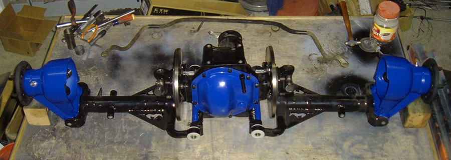
Let's use the position of the LCA/bone as an example I noticed it being in many positions in pics I have seen. So I questioned it. I posted pics and what seems to be some professional sketches. I posted a Jag IRS builders own words stating the halfshaft is not to be pointing downward toward the third member. irstang has now added to this. My purpose for posting this issue is not to prove someone is wrong, But I feel here is the place to get the right answer, to be clarified. Just saying no it goes this way is not proof, find the info and report back. I seek no more than this site to have good solid info and that's why you are wrong.
Last edited by Daze (3/20/2012 8:35 am)
![]() Offline
Offline
If you actually spent half the time working on your kit car that you do on line you might have it done . But you seem to prefer criticizing the efforts of others while you have yet to do any thing more than cut off the shock mounts on your car. Kind of funny dont you think?
Last edited by tyrellracing (10/27/2012 6:22 pm)
![]() Offline
Offline

Ralphy and tyrellracing, THAT IS ENOUGH!!!!!!!!!
You both have a lot to offer he forum. Much of the information on these pages weather original technical concepts or links and pictures from other resources is due to the two of you, and that I appreciate BUT this bickering I am reading in this thread WILL STOP. I have no problem with a heated debate as long as it is in relation to "Forum dedicated to installing, rebuilding upgrading, tuning and/or racing of any IRS unit on any vehicle regardless of IRS type or vehicle make and model!" However insults and potshots are not tolerated on this forum. I don't care who started it, I don't care who is wright and who is wrong. On a forum there is no body language so it is easy for two people to have a misunderstand and have it blow up in to something much bigger. I don't know if this is how this got started or not and I really don't care. It ends right here right now. NO MORE PERSONAL ATACKS!!!
I apologize to every one else on the forum that I did not catch this sooner.
Last edited by Daze (3/20/2012 8:37 am)
![]() Offline
Offline

Jim,
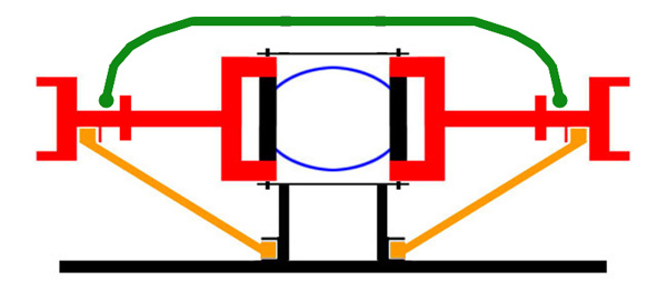
You've got into the discussion about harmonics. With running the long arm short arm double wishbone. Would you not think the difference in length aids in the removal of said harmonics? Being that they are two complete different lengths would setup two different harmonic patterns, frequencies or what ever the term would be? Maybe you already posted this? Plus the fact adding a second arm removes app. half the load off the existing arm. It would also seem if you were going to try and match the two harmonically. It would be a harder task than not.
Ralphy
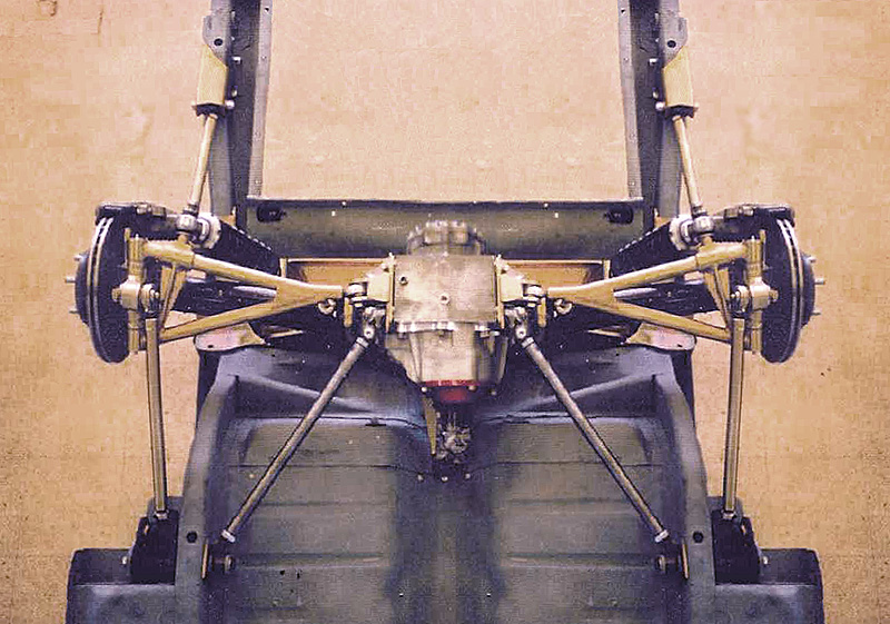
This is the design TR is talking about. Not his however.
Last edited by Ralphy (3/20/2012 11:44 am)
![]() Offline
Offline

irstang wrote:
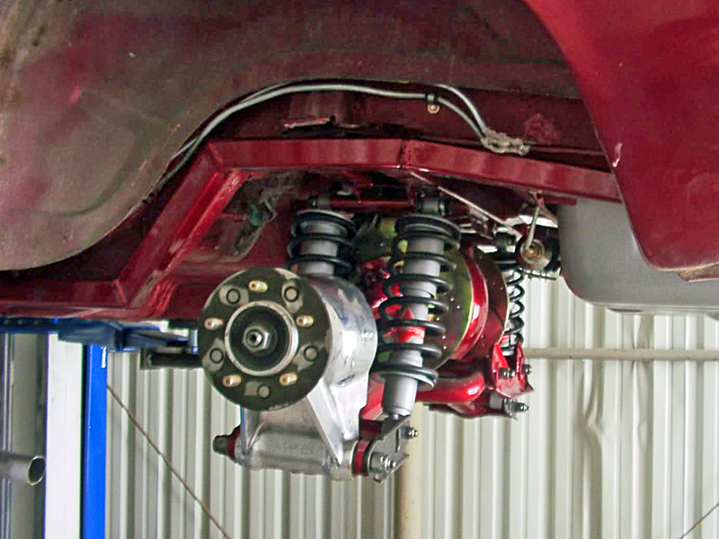
1965 Jaguar E-Type Lightweight-Style Vintage Racecar
I found this picture of a Jaguar lightweight racecar rear suspension set-up for racing on Hemmings. This car is running the half-shafts horizontal with 3 degrees of camber. Coil-overs are 825 pounds per inch. I calculated 500 pounds/inch at the wheel on a 2350 pound car! The description of this car is good reading:
I like the radius rods and carrier support. The bearing air ducts are definitely cool.
That would be a great rear end to see in person. I especially like the tubing welded to the wishbones between the shock mount and the differential pivot to strengthen the set up. I would also love to know where he got his vented rotors from.

![]() Offline
Offline

Well, assuming that the resonance that you are trying to tune out is wheel hop, a good first step would be to try to establish what that frequency is, and if possible determine a range within which wheel hop can be sustained. Just at a guess I'd say a typical resonance might be around 2 Hz (two cycles per second or two hops per second) but TR might be able to give us a closer approximation due to his long battle with it.
It takes a very large mass and a pretty big spring to get 2 Hz, and a lot of the smaller bits are just going to be going along for the ride. Whether a second arm contributes, dampens, or does nothing will largely depend on how and where it is attached. All vibrations have a sine wave pattern if they consist of a single primary frequency. Therefore they have peaks and nodes, and this pattern is set up in a standing wave going down the part that is vibrating. Sometimes you can see it, sometimes you can't, and the direction in which it is oriented makes a difference. Anyway, if the second link happens to be attached at a node or dead spot then it will not affect the resonance. If it is at a peak point then it will affect it greatly, primarily by changing the resonant frequency but may also have a damping effect as well.
So if the wheel and tire is the mass and the LCA is the spring (although as rigid as the Jag LCA is I still have a little trouble seeing where this could generate enough of an excursion given the weight of the wheel/tire to create a sustained 2 Hz resonance) it is probably impractical to change the mass enough to reach the limiting point and that leaves the spring (LCA in this case). Obviously this is all complicated by the dynamics of the tire itself but as little can be done there either we're back to the spring.
The next relevant question is, does the wheel hop occur on the right side only, both sides, or on the left? This can tell us a good bit about what components are involved in the oscillation. Another very useful technique might be to mount a camera where it could record the differential to see if that moves.
If we think of the vehicle as a whole it soon becomes clear that the body and frame are not rigid and may be contributing to the oscillation. For instance, many vehicles exhibit some twist or wind-up in the body on a hard launch. This quite obviously has the effect of a very large spring and of course the body is a very large mass.Then from that point to the contact patch every connection needs to be evaluated for compliance in light of the location of the wheel hop and the axis of motion. In all probability the movement cannot be isolated to a single component but will involve a number of connected pieces. By comparison an ox-cart suspension is pretty easy as leaf spring wind-up is the obvious culprit, but here we have no such dynamic and must look elsewhere.
I would think we'd want to look for a characteristic of "springiness", and something capable of storing an amount of energy and motion equivalent to the ox-cart spring. I do not think the LCA is capable of doing that under the level of torque being applied to it, and further feel that applying enough force to make it deflect enough to absorb that much energy would very likely result in permanent distortion or bending. It's design does not make a very good spring, nor does it's materials. Likewise the uprights. Nor for that matter do the diff housing or the lower brackets, despite the less than desirable attachment. Each one does contribute some to the whole but even added up it isn't going to be enough. Add in bearing compliances and we're getting closer, and that leaves mountings and then frame and body rigidity. It may even be that the entire rear suspension is pivoting in place during wheel hop, or the suspension may be moving in an unexpected axis or direction.
I don't know how much this helps, but it is at least another way to look at the problem. The thing to keep in mind is that with so many elements involved in setting up the resonance, there is very likely to be one or more key elements that can tune it out with a relatively small modification. The trick is finding out where that key is located.
Jim
![]() Offline
Offline

WOW! You took the words right out of my mouth. That's what I was about to say! ![]()
Seriously though, I really enjoy reading your posts. I was able to follow your writing fairly close. The remainder is my abilities.
How many coilovers are you running? Your pic shows two up front. Many of the setups I have seen with a single LCA run only the two in the back.
Hey Jim, wasn't your car a team project? Are you not a teacher?
Check your in box.
Ralphy
Last edited by Ralphy (3/20/2012 6:16 pm)
![]() Offline
Offline

Not sure about this one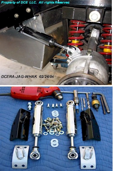
ERA Jag Rear Wheel Hop Absorber Kit by DCE LLCorp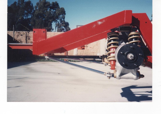
Last edited by Ralphy (3/20/2012 10:30 pm)
![]() Offline
Offline

Two cars Ralphy, maybe that was the cause of the confusion. They are very similar but very different. The group project is a 455 Buick/T5 and runs UHMW outer pivot bushings and is a hard top (GT). It has been on the road since about November and is now in Kingsport, TN and will be all over the country in the next few years.
My own personal car is a convertible and the upgrade from a Buick 215 should be completed this summer. It runs a blown, injected and intercooled 340 Buick/AA80E 8 speed and timkens. Both cars run an oil bath in the rear spindle bearings which allows a little more preload and gives a stiffer assembly. Both cars run a single pair of coil-overs with around a 300 lb spring. Both cars are fitted with a nearly identical bolt-in Jag IRS conversion.
I've heard the justifications for double coil-overs and I just don't buy into it for this light of a vehicle. The loading by the spring set to one side is nowhere near what the pivots will see from acceleration and braking in my opinion so I feel those concerns can be summarily dismissed. They are where they are purely due to packaging concerns, so we could retain the stock fuel tank, battery boxes, and not modify the body to bolt in the suspension, but since then I've realized there are any number of justifications for doing it that way. For instance, note that the pivot bracket bolts are positioned at the front of the bracket so the assembly is stronger with the shocks on the front.
Teacher? Where did that come from? Well oK, I did get a teaching certificate a few decades ago. I also got a law degree and filed patents. I also professionally guided white water. And did a whole bunch of other stuff too including running a business as a prototype developer. For a real challenge that one will do it. What I never did get the hang of was making money so everything I do is on a shoestring. (I guess to make money that has to become your overriding priority and I never gave it much thought.)
Back when Arthur Mitchell donated his Arntz/Butler front suspension to the Roadmaster cause (replacing it with the Fast Cars IFS which was developed specifically for the MGB) I think I may have spent some time on that Cobra site, and the later replicas really are some very nice cars, plus the earlier cars have a lot of historical value. But, I always felt like I'd be giving up too much by going to the Cobra from the MGB. Back in the day, the MG was a much more civilized car than the AC, and much more modern as well with its monocoque structure, which was and still is remarkably stiff. We have found it to be capable of handling very high power levels without any need for reinforcements and the only thing lacking once we got to that point was suspension. Options exist of course and Jag units have been fitted before, but as things now stand we do have a very good package and the result has been a remarkable car. The next few years should be interesting to say the least.
Jim
![]() Offline
Offline
irstang wrote:
1965 Jaguar E-Type Lightweight-Style Vintage Racecar
I found this picture of a Jaguar lightweight racecar rear suspension set-up for racing on Hemmings. This car is running the half-shafts horizontal with 3 degrees of camber. Coil-overs are 825 pounds per inch. I calculated 500 pounds/inch at the wheel on a 2350 pound car! The description of this car is good reading:
I like the radius rods and carrier support. The bearing air ducts are definitely cool.
Along the lines of that 1965 E-Type, here's another that I enjoy looking at:
![]() Offline
Offline

I've been thinking about this torque applied to the LCA. The one design feature of the Bolt-in Jag IRS for the MGB that has the biggest potential to control wheel hop is the forward extension of the inside pivots.
This is a long 5/8 or 3/4" stud made from drill rod that is almost 3 feet long, running to a forward crossmember, but it also runs inside a reinforcing tube that acts as a compression spacer, along with the entire pivot stack and the front heim joint. So when tightened down it pre-stresses the stack, much like a pre-stressed bridge's roadway, essentially adding a 3 ft solid arm to the LCA. This, more than anything else is what I would credit with our lack of wheel hop.
Thinking about the forces applied, the engine has 500 ft/lbs and then just for convenience figure a 10x multiplier through 1st gear and the diff, so 5000 /2 for 2500 lbs applied to each tire patch. The same force is applied at each hub which is 6" above the LCA. So that is 1250 ft/lbs applied to each LCA, or roughly 1250 lbs across the wide end of each inner pivot which is something close to a foot across. Well, 1250 lbs is not going to be enough to deform the ends of the LCA. It is plenty stout enough to take that and would probably be up in the neighborhood of 20 tons before we'd see it move very much. Same for the outer end and for the upright. I think we can assume the bearings will take it as well. So the movement has to be from there inwards and the obvious suspects are the pivot bracket attachment bolts, and the body or frame mounts.
By attaching a 3' long lever to the inner ends the load is largely removed from the pivot brackets, and what is not cancelled by counter torque is connected in a rigid manner to the body. I do not recall the diameter of the pivot tubes, maybe 1-1/8" or so, but that is certainly large enough to take the load. So the wheel hop stops right there, before it even has a chance to get started. The entire assembly has been made orders of magnitude stiffer, moving the resonant frequency well above the range of wheel hop. This is why we don't have a problem, and the fix is a relatively simple one.
Now it may sound and look like I came upon this as a fortuitous accident and if you think so you can be excused. However, I have been designing mechanical mechanisms and systems my entire life. I rarely rely first and foremost on analysis and calculation, rather I have developed an intuitive understanding of and a feel for the qualities of the materials involved and I design them to work harmoniously together. As in this case, the analysis usually comes later to refine the understanding of what is taking place in the piece.
Now this is not the only way to skin a cat by any means, but it does make use of a fundamental principle. To increase control, use a longer lever. Reduced to it's simplest terms that is exactly what I've done here, and it was done intentionally, realizing early on that there was a deficiency that needed to be addressed, and that one structure could supply two needs, that being to stabilize the LCA in both the rotational torque axis and in the vertical axis. My new LCA design improves the structure, making it both more rigid and lighter.
Jim
![]() Offline
Offline
No comment
Last edited by tyrellracing (10/27/2012 6:25 pm)
![]() Offline
Offline

Easy TR, let's not go there again, OK? Start fresh maybe?
I completely agree that the attachment to the diff is less than it could have been. But, that did allow for two angles by simply reversing the brackets. Now if those four bolts had been all there was, (and in far too many street rods it is) there would have been trouble. It was not. The cage and the bottom plate provided a large structure that the diff was tied into top and bottom, and the pivot shafts locked into it at both ends. So the LCAs were not going anywhere that the cage didn't also go. The diff was merely going along for the ride and for that the 8 bolts were quite enough. But remove the cage and all of that changes. A tie bar or two and a strut or two don't even come close to offering the same rigidity, and although it worked OK in a super light weight T-bucket, looked great, and lured us into a false sense of security, the necessary structure just isn't there and it just isn't adequate for anything more demanding. Even so, there is a simple solution. I've already described it, there should be no need to do it again.
Jim
![]() Offline
Offline
No comment
Last edited by tyrellracing (10/27/2012 6:24 pm)
![]() Offline
Offline

Makes sense. Now about that tensile loading on the pivot bracket bolts, that is the purpose of the aftermarket tie bars between the inner pivots.With substantial tie bars (and the cage provides the same function) the tensile force that would otherwise pull on the bracket attachment bolts now simply clamps the opposite side pivot bracket more tightly against the differential housing. Which means that the forces you say are predominant have no net effect. It really is a remarkably well designed system, and I doubt all of this was thought out in the initial conception.. At any rate, taking the same 500 ft/lb example, we have 2500 lbs of linear force at each wheel hub and also on the outer end of each LCA Using guestimates for the dimensions, say we have a 2 ft long LCA and a 6" distance between the attachment bolts that would be a 4:1 multiplier not taking into consideration the seat area of the bracket, for a maximum tensile force on the bolt of 10,000 pounds. With typical fastener strengths being in the ballpark of 80,000 to 130,000 psi and the effective area of a 7/16 bolt being much less than one square inch, it would seem logical to think that the tensile stresses on the bolt would be excessive. Until you consider the tie bars. At a 1 ft distance apart that 10,000 pound linear force is now only 5,000 lbs and the typical Jag aftermarket tie bar is more than adequately designed for that much pressure, whether in tensile or compression. So again, we have load sharing between the bolts and the tie bars and the proportions depend on the amount of give in all of the components, but since the pivot rods are in line ahead of the pivot brackets they will take more of the load. The result? The attachment bolts are not overloaded in tensile stress, and as we have seen earlier, they are not overloaded in shear due to the cage. Nothing reaches the stage of plastic deformation and no damage is done. As for the aftermarket use of tie bars and struts to replace the cage structure... well that is partially effective but the objective clearly is poorly understood based on the existing designs. Most seem to be either an attempt to mimic the supplemental braces tying the cage to the stock body tub, or an attempt to replace the reinforcement provided by the transverse diagonal edges of the cage itself. Occasionally will be found some structure designed to limit rotation of the differential housing, and rarely, one that does so by capturing one end of the inner pivot rods. I can't say that I've seen even one design that has tried to do all three at the same time, and here's another clue. If you only limit one end of the pivot rod, what do you think the other end is doing? Trying to wobble the pivot bracket bolts up and down maybe? Yeah, I'd say so. And the installations that use the entire ugly cage still typically try to mount it on the OEM bushings, may or may not install the diagonal links to the LCAs, probably use the compliant bushings if they do and attach them in the wrong place, and may not use anything at all to limit cage twist. All of which makes it pretty obvious that they do not understand the dynamics.
Now as to the plasticity of metals, I completely agree, however we may not see eye to eye on how much force is required to get deformation and deflection. This is however a matter of exact science and any disagreement between us on the issue therefore must be a matter of opinion and possibly insupportable opinion at that . When you get wheel hop, how far does the hub move in relation to the body of the car? Is there relative motion fore and aft? (In conventional tube axles there most certainly is, and a lot of it.) If you are applying no more than 1-1/4 tons of force to the wheel hub, given the mass of the components between there and the differential, material deflection is NOT going to be enough to account for it. At least half of the forces are in compression. Compression deformation for cast iron and aluminum requires vastly more force than tension if only due to the much larger areas involved, and even so even the softest aluminum alloy is probably going to exceed 15,000 psi of tensile strength, and the cross sectional area of any part of the structure is going to be such that the calculated forces are insufficient to cause more than a very slight deformation of the part . As we've shown, the tensile forces are well below the stretch level and most is converted to compression force by the structure. Torque forces are likewise tied into more substantial structures designed to handle them. The LCA is NOT going to deflect more than minimally under even 5 tons of force and that is well in excess of the combined linear and torque stresses. So I simply cannot buy into your argument that deformation of the LCA, upright, and related parts allows enough movement to cause wheel hop. The structure is too rigid to allow it, and it has to be coming from somewhere else. Like an improperly designed support system.
Regardless, you have cured it with your top link so presumably all is right with the world, but at this point you have no valid basis to claim that the basic Jag IRS cannot avoid wheel hop without a top link, even though you were unable to do it. Like I said, this cat can be skinned in different ways.
Jim
Last edited by Jim Blackwood (3/25/2012 1:25 pm)
![]() Offline
Offline
No comment
Last edited by tyrellracing (10/27/2012 6:10 pm)
![]() Offline
Offline

Interesting points TR. Well, if you do get deflection readings I'd be interested in seeing them. Any chance of getting a photo of your test setup?
Jim
![]() Offline
Offline
No comment.
Last edited by tyrellracing (10/27/2012 6:37 pm)
![]() Offline
Offline

Sounds like a decent setup, at what point did you apply the load? Vertically somewhere along the beam of the LCA?
I know it would be a difficult test to set up, but it would be great if we could immobilize the inner pivots and apply the load horizontally against the outer end of the LCA, as that would be a lot closer to simulating the linear acceleration forces.
Jim
![]() Offline
Offline
No comment.
Last edited by tyrellracing (10/27/2012 6:38 pm)
![]() Offline
Offline

Sounds like a good plan TR, It would be great to have real test data and know exactly what we are working with. Still, there is relevance to the test you have already done, in that it shows half of the picture in regards to torsion loading.
Jim
Last edited by Jim Blackwood (3/26/2012 6:40 pm)
![]() Offline
Offline

Jim,
Maybe I'm missing what your trying to accomplish. But can't you chock the front tires and/or pull against a wall. Then load the rear in some way running or wrenching the motor over. And measure the spacing between the tires and fenders, before and after?
Last edited by Ralphy (3/26/2012 8:30 pm)
![]() Offline
Offline
No comment
Last edited by tyrellracing (10/27/2012 6:39 pm)
![]() Offline
Offline

If your fixture is rigid enough to resist the rotational deflection, it should be fairly easy to either attach an arm, or simply extend the outer pivot bolt far enough to move the tip of a dial indicator. The indicator itself should be mounted on an extension of the holding fixture so any relative motion is between it and the far end of the LCA is measured. This would include any bearing slop in the measurement but that should be taken up at the beginning and you could then zero out the indicator again if you wanted.
Ralphy, the whole idea is to get a test setup that is rigid enough to measure deflections on the scale of .001" resolution in order to see how much each piece is deflecting. By doing that we can see how each component contributes to the whole, making the problem areas pretty obvious and then we can come up with solutions that we know will work. While the approach you mention is valid, it is difficult to get readings on the individual pieces. Certainly it would work well for overall measurement and that is also something that would really help a lot, so really the ideal thing would be if we had both.
Jim
![]() Offline
Offline
No comment
Last edited by tyrellracing (10/27/2012 6:40 pm)
![]() Offline
Offline

I picture a flanged shaft app. ? 2 ft. long with an eye bolt at the end, bolted in place of the wheel. That corner of the suspension freed on 3 tires at ride height. Plus the fourth on casters to roll. A flat 24" wide board also in place of the wheel marked on the ground another board. Like others use for alignment. A one tenth digital level, a come along, indicators with magnetic base and a pull type scale. Seems you could gather a whole lot of info at the same time. But how do you simulate weight transfer? Start throwing steel in the trunk? Then also find something to attach that come along to. You can gather data at different points before and after with the level and all.
The neighbors will surely think your nuts. So at minimum you will keep them from pestering you or borrowing things. Maybe crank the radio up loud also and bust out some beers. Yell once in a while, HEY WATCH THIS! LOL!
The one place you may get a false increase is the upright twisting. I think there's something to the fact a tire contacting the road over a wide area. Gives it a tendency to want to track straight. Somewhat reducing the twisty loads.
Ralphy
Good Luck!
Last edited by Ralphy (3/27/2012 12:19 pm)
![]() Offline
Offline

Ralphy, If you'd like to try it that way I'll do all I can to assist. What I see as a problem is the squishy nature of the test in general. Tires squirm and move, bodies twist, bushings give, etc.. But, for that particular vehicle those must all be dealt with so the test is still valid.
Jim
![]() Offline
Offline
No comment
Last edited by tyrellracing (10/27/2012 6:40 pm)
![]() Offline
Offline

Jim,
I agree with so many variables. It seems to me anything short of video taping your suspension in action or building a high dollar test bed would maybe give false numbers. Having forces in compounding directions and a handful of parts. The bone alone is what, three pieces? For me, I would like to see whats happening, video taping may reveal see-able unwanted motion. I think TR mentioned this. If you had a trustful friend you could put behind the wheel and load your drive train stationary. Maybe something would jump out very noticeably this way also. Unfortunately we do not have budgets like manufactures have.
Ralphy
I hate tax season! I still have to redo all the medical bills, wish I had kept better control.
Last edited by Ralphy (3/27/2012 6:26 pm)