
 |
 |
 |
 |
 |
You are not logged in. Would you like to login?

![]() Offline
Offline
I am nearing the point when I need to really consider what the uprights will look like on my new IRS.
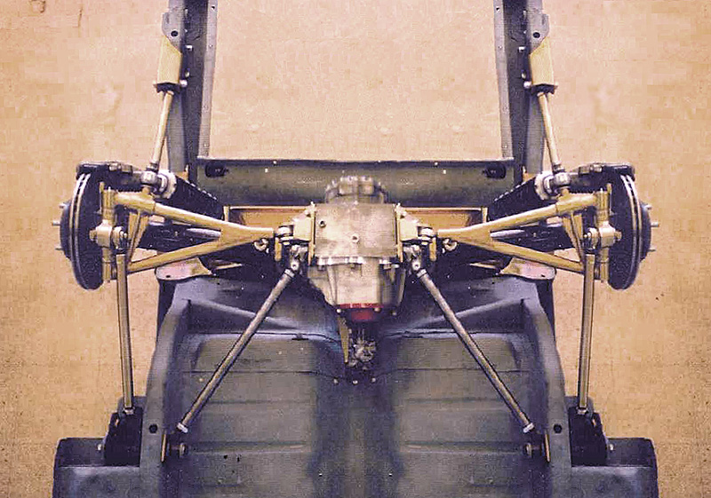
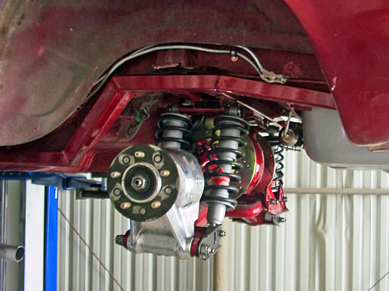
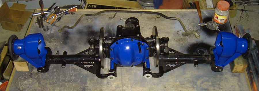
Rather than plow entirely new ground, I took a journey courtesy Google and Bing, and found a number of example. I will present them in a series of posting in this thread.
First, as I am designing/building a new suspension for my C3 Corvette (one owner 1978), it is probably useful to understand why I am doing this. I am interested in initially engaging in HPDE, and eventually track days, and as energy, experience, and expenses allow, competing in either SCCA, NASA, or other forms of road racing. I have done a number of autocrosses in the past, and while enjoyable, I now want to move on to other events.
My first thoughts were to follow a straight Corvette approach. I modeled and built a "Jim's Giovanni" some documents elsewhere in this forum, and then realized I wanted to eliminate the standard C3 Trailing Arms too.
My research led me to a number of alternative approaches. One, mount a C4 rear suspension to the C3. That has been done successfully by others, but not quite the engineering challenge I guess I was looking for.
Another approach build a mounting structure (subframe) for a C5 or C6 IRS for my C3. Not done yet really, but very do-able. Unfortunately, my investments in a new set of 1/2 shafts (telescoping), rear differential(4.11), brakes, bearings, and spindles, sort of ruled out using a used bit of C5/6 gear.
But this research did lead me to settling on a double wishbone approach. The question still remained, "What uprights to use?"
In the Corvette-only approach the viable uprights are based on the C3 bearing carrier. The Greenwood,


and Pier Palou's approach (Stroker-427)


approaches both improve the rear suspension, and still use the bearing carrier - more or less.
More results to come!
Cheers - Jim
![]() Offline
Offline

Continuing my review of options, I have been frequenting the LOCOST Forums. 
BTW, This chap has a complete layout on the LOCOST site for the entire build! (FREE!)
These are DIY-ers from around the globe building their own cars, some race. 

Most all scratch built and somewhat replicate the Lotus Super 7 -- a car I always wanted to buy. 

There I came across a number of approaches to the uprights - many have some distinct advantages too.

On the down side, the LOCOST approaches, tend to be a bit low powered,
so some engineering may be required for structural integrity, and occasionally the projects go on forever - no time limit.
Again - more to follow on this review of Upright approaches!
Cheers - Jim
Last edited by phantomjock (2/07/2012 3:57 pm)
![]() Offline
Offline
The LOCOST, being a "plans-only" approach, there naturally other examples out there.
In my research of other similar efforts, I came to the GT40, 

A Scratch-Built Lola, 
a Hemi-equipped Pantera in Sweden


Even the venerable COBRAs (smile Ralphy!) OOPs it wouldn't post --
Each of these have some interesting Design Attributes for consideration in choosing what shape or style of upright for my IRS.
Again, time limits are not always imposed on these self-initiated projects, but cost is frequently a major consideration.
Just a few more to go!
Cheers - Jim
![]() Offline
Offline
Continuing on a quest again for more innovation, the Formula SAE challenge yielded some fruit as well. 
In this college and university engineering students design their race cars.
They need to keep costs down, being innovative, 
very competitive, and there is always the opportunity for some breakthrough thinking.

The FSAE program is on a time schedule but the students frequently have access to some high quality machining and top of the line software for analysis.
OK - One more lap!
Cheers - Jim
![]() Offline
Offline
My last set of Uprights I chased down were those designed from the get-go as race equipment. 
They are off the shelf. 
Naturally, they tend to work. 
After all, if your business is to build a race part - if you want to stay in business--it had best work and not fail first time out. 
They tend to be high end designs, innovative, and a bit expensive. As a design effort some could be replicated with a bit of skill.

Now, If I planned on a Land Speed Record - I'd want that one from Project Bloodhound!!
So, there is a start at Upright designs I found. Please add more as you find them.
I focused on REAR only, but realize many of the same design attributes that make a good front upright can be used in the IRS too.
Note the Corvette C5 and C6!
Cheers - Jim
![]() Offline
Offline

PJ,
Do you have a link to this guys postings at Locost? I don't know why but both my computers crash on some pdf files. Anyone else have this problem? I think it may be older formats.
I think I found a way to view Rorty.
Last edited by Ralphy (2/08/2012 8:48 am)
![]() Offline
Offline
About 1/2 way down - download the pdf then open it?
Maybe a browser problem not supporting the pdf extension. If mozilla/firefox theyu have a plug-in available.
Cheers - Jim
![]() Offline
Offline

That page, I have been there before. In fact it looks like I had opened it once.
It does the same with FF or Explorer. Acrobat Reader would not update for the last two months. Saying I had no authority. Today I got the update loaded. Runs longer but still locks up. I got a message after two minutes Acrobat Crash? I don't know? I do have a 64 bit PC.
Some PDF's open some don't?
Last edited by Ralphy (2/08/2012 3:43 pm)
![]() Offline
Offline

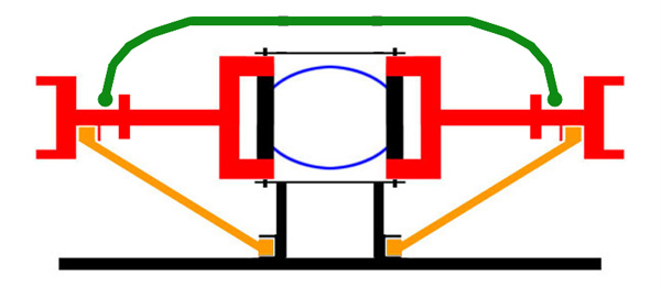
there is something about this one that really speaks to me. I like the quality and the obvious DIY aspect
![]() Offline
Offline
Me too - I'm going to get some foam core this weekend and do some "folding" origami exercises.
I want to mount with double shear but I like the depth for wheel offset too. Its a nice build.
The integrated caliper mount is a sweet idea too. He's done a bit of thinking for many of us!
Cheers - Jim
![]() Offline
Offline

Looks like his caliper and rotor are not matching up? Unless he plans to run bigger rotors. The C3 Calipers are big /long. Think that Wilwood is big enough for a Vette Jim? I wondered if the C3 rears were a little over stated in size?
Ralphy
Last edited by Ralphy (2/10/2012 9:56 am)
![]() Offline
Offline
Good eye - the caliper does look a little oversized for that rotor.
I think there is always room for more stopping power. Also, note the trend to putting C6 rotors/calipers on c3s too.
My Aerospace aren't as large - but will be adequate. The caliper mount as part of the upright is a clever bit of design too.
![]() Offline
Offline

Yep looks like the diameter is off by about 2" but I am sure whats in the pic is just there for mock up. As to the wilwood parts I am a wilwood dealer and can hook you up with anything wilwood sells, at good price so let me know if you need anything.

![]() Offline
Offline

I have a pair of billet aluminum upright blanks that I had waterjet cut if anyone is interested in them. I had them made up similar to the layout of the T-Bird but flat, I think the billets are a little over 2" thick. They need to be finish machined of course. I'll take a hundred bucks plus another 25 for shipping for them, which is less than they cost me. When I decided not to use a top link they became redundant but I figure it would be a good start for one of you guys.
Jim
![]() Offline
Offline

Can you post a picture Jim? What type of material are they made of?
Ralphy
Last edited by Ralphy (2/15/2012 6:47 am)
![]() Offline
Offline
Yes! Pictures Please. And details!
I sense a bidding war?
Also, if you could offer some dimensions too.
Maybe a diagram/engineering drawing used for the water jet setup?
Cheers - Jim
![]() Offline
Offline


I've got no clue what ever happened to the cam file and don't recall dimensions except that they were rough-out dim to match the Ford parts. Hope this works, I laid a yardstick across one of them.
Jim
![]() Offline
Offline
Hey Jim
Thanks for posting. They look plenty stout.
I bet someone will find a good home for them too.
Cheers - Jim
![]() Offline
Offline

I was hoping for enough meat at the outer bearing to use the C3 bearing. But? Looks a little close don't you think PJ? The size I am referring to is the OD, looks to be app. 4".
You can put the pic and description in the classified section also.
Ralphy
![]() Offline
Offline

Ralphy, the OD of the bearing boss area is 4-1/2" plus maybe ten. What is the diameter of your C3 bearings?
Jim
![]() Offline
Offline

Ralphy? You there?
Jim
![]() Offline
Offline

I couldn't find that other post. Anyway if the hub bearing BC is 4 to 4.25" it should work out depending on the bolt size. I measured the distance from the bearing bore to the LCA pivot and 2-1/4" would put everything at about center. Of course it could be moved up or down about +- 1/2" or so. Distance to the UCA pivot would be about 4 to 6". These could be sculpted and polished into extremely nice show pieces if someone wanted to take the time to do it, and like I mentioned they were intended for inboard brakes and maximum length control arms to get as much suspension travel as practical.
Jim
![]() Offline
Offline

Jim,
If my BC was 4" and the bolts were 3/8". The outer edge of the 3/8' tapped holes would be 4 3/8". Looks to me like you have an OD of 4 3/8" to 4 5/8". Then I would have to counter bore or pocket the ID out to at least 4 5/8" I'm guessing. To clear the bolt head. That leaves little to none for wall thickness.
Here is a pic of an aftermarket upright, you can see I would need more like 5" plus OD.
Ralphy
Last edited by Ralphy (3/02/2012 2:35 pm)
![]() Offline
Offline
You got a better link to that - and the aftermarket source?
Not fond of the "mounting in single sheer" but nice looking product.
Looks ready-madefor a C3 application too.
Cheers - Jim
![]() Offline
Offline

Yes, go to the chevy IRS thread. Fourth post, with link and all. Dick Guldstrand design. And yes it is a C3 swap. I also see they raised the price, it was $2,700 now $3,300. It's sold as a leaf or coil-over design. However TT at VM said they told him not to use the coil-over setup.
Last edited by Ralphy (3/02/2012 4:37 pm)
![]() Offline
Offline

I think it was 4.510" +_ .002" but I could get a more accurate measurement if you wanted. Doesn't sound like it though.
Jim
![]() Offline
Offline

Here is the Guldstrand upright again PJ. I just noticed the caliper mount is part of the upright. So the additional plate is not needed. PJ, what if a person was to copy this and instead of having the two lower camber rods. You left the front where it's at. Then moved the rear behind the half-shaft? Like the C4, but the lower would be forward instead of centered under the half-shaft?
As I mentioned to JB, distance between lower and HS is 6 5/8" app. He says his T Bird copy is only 2 1/4", just think how much stronger that T Bird setup is under acceleration. That's why I like the C4 having the toe rod behind the HS. No twisting of the upright.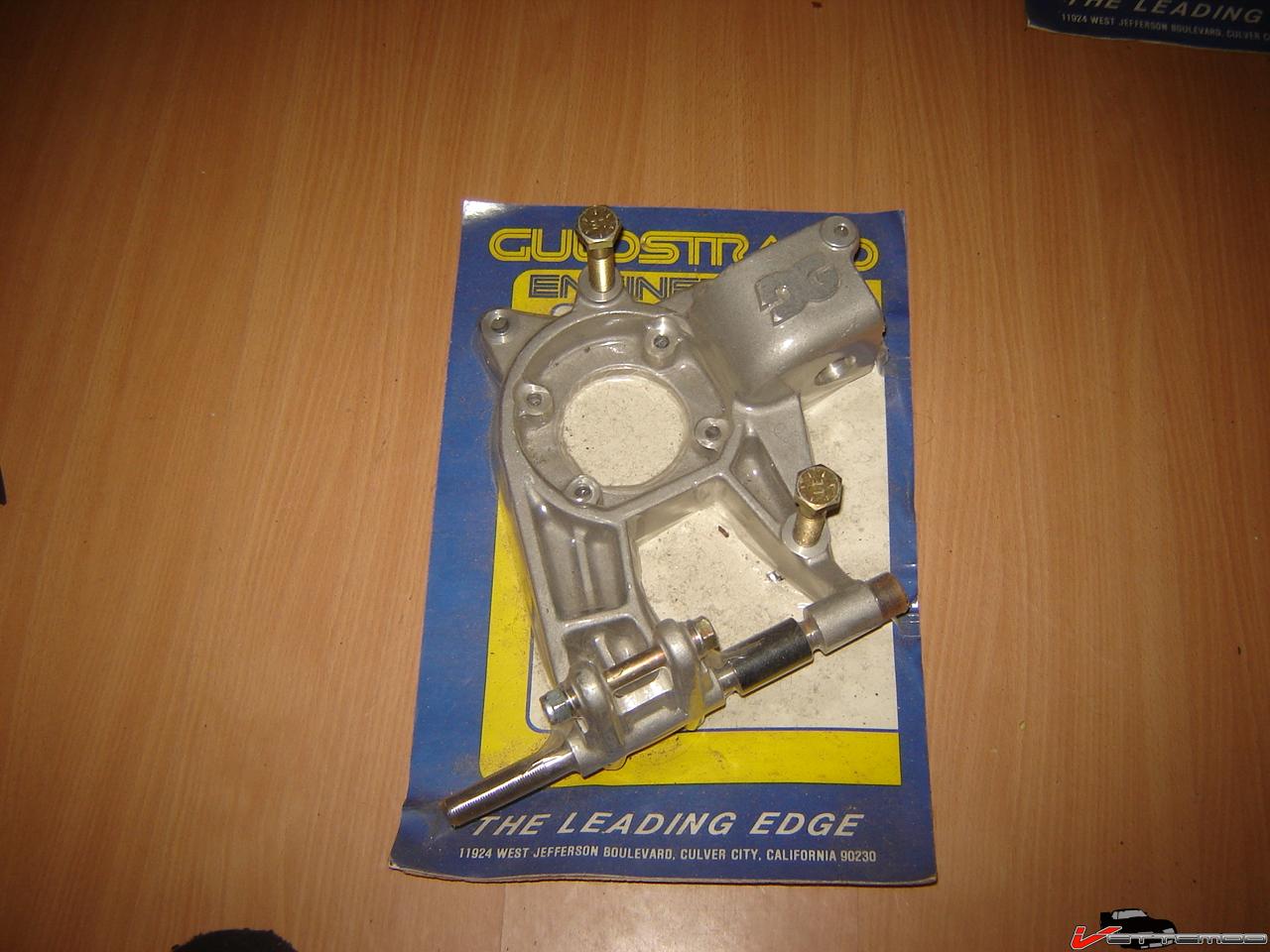
Rain woke me up!
Last edited by Ralphy (3/03/2012 1:49 am)
![]() Offline
Offline

What do you think of this C3 conversion PJ?
Last edited by Ralphy (3/03/2012 2:04 am)
![]() Offline
Offline

Ralphy wrote:
I was hoping for enough meat at the outer bearing to use the C3 bearing. But? Looks a little close don't you think PJ? The size I am referring to is the OD, looks to be app. 4".
You can put the pic and description in the classified section also.
Ralphy
If the C3 bearing carrier was rotated 45 degrees the top and side bolts should go right through the meat of the upright blank, leaving the bottom one with maybe a 1/8" wall. That could be easily heliarc welded to add a pad for the bolt head. At around 2" thick there is plenty of meat.
Jim
![]() Offline
Offline

It occurred to me recently that most modern high performance manufacture IRS suspensions have a common trait. Which is a single mounted upright at the LCA and the UCA and they all use a separate toe rod behind the halfshaft. Cars included are the Corvette, Cobra Mustang and Dodge Viper. Reasoning may be to remove any twisting of the upright with higher powered motors. Corvette has been using this type of toe control since the C4. Just thought I would throw that out there.
Ralphy