
 |
 |
 |
 |
 |
You are not logged in. Would you like to login?

 1 2 Jump to
![]() Offline
Offline

PJ,
I started with doing spreed sheets at work with our FIFO line. I have a co-worker who is was a Black-belt. He used Excel a lot.. I created a couple of spreed sheets for my taxes using basically the sum feature. I was playing with the trig feature and stopped at the angle thing. Reading how Excel uses radians not angles. However, the BonesApart seems more advanced than what I could create anyhow.
Ralphy
![]() Offline
Offline

husker,
The BonesApart calculates your roll center also on page three or one.
Ralphy
![]() Offline
Offline
I'm more of a graph paper and ruler sort of guy. But now that I have these different tools might be a little more fun.
![]() Offline
Offline

LOL!
You came a couple of months late to see my crappy graph paper posts. Just dig back a little.
Ralphy
![]() Offline
Offline
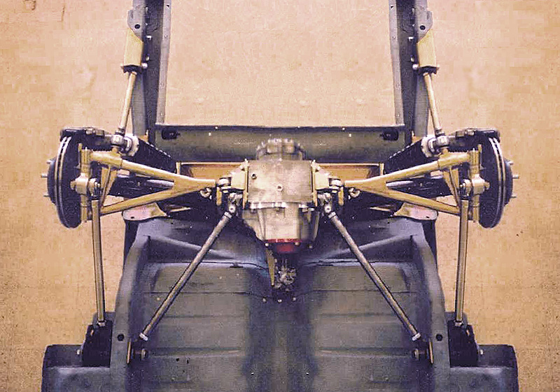
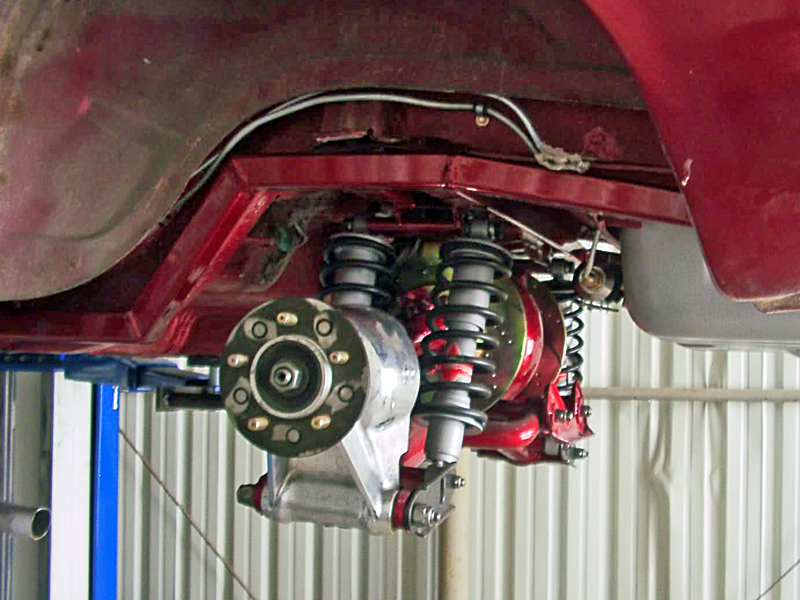
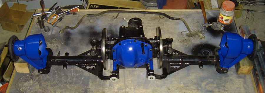
I got some rough assembly done today to try this. I started with the axle at level and the flange at 90degrees.
This is at full UP and the inner Ujoint hitting the LCA. 6-6.5" Up from level
The Ujoint is at or near bind also at this point.
There is about8.5 degrees of rollback on the flange in the Max UP position.
I know Im not supposed to but I can only assume it will be the same 6" DOWN to Ujoint Bind in the low position. I just wont have it anywhere I can get the framework high enough real soon to find out for sure.
![]() Offline
Offline
That shows some promise. One thing that worries me is the camber curve on the lift side of things. It will go positive I believe. It will depend a lot on how much. I know I saw something somewhere, gonna have to dig.
![]() Offline
Offline

looking good. Does it really matter if the camber goes positive when you lift?? I thought that was only going to happen when going over speed bumps and such so at that point a little positive camber should not be an issue.
![]() Offline
Offline
Depends on how quickly and how far it goes, if it is only a couple degrees at say 2-3 inches above ride then no it isn't a big deal but if at 1" above ride height it goes 5 out then that is gonna wear tires pretty quick. I don't think it is going to be enough to matter.
![]() Offline
Offline

Playing with BonesApart, most configurations go positive oh just slightly, initially. As rebound increases, camber starts back negative. Also most setups start negative, C3 calls for minus 0.5.What does Jag call for?
Last edited by Ralphy (2/21/2012 8:22 pm)
![]() Offline
Offline

here Husker this ay help 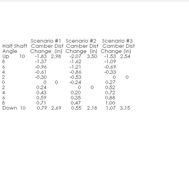
this is the stock Jag camber curve with camber set at 0º with different angles on the suspension.

![]() Offline
Offline
There is kind of a big sweet spot in there where the camber doesnt change much. Something the pics dont show well also is the inwards movement of the hub. It burned up most of the 2"+ gap it had from the frame in the UP. I'm going to play with it some more when I get a chance. thinking some type of air strut or whatever might be something fun to play with or allow for,
Last edited by Digz (2/21/2012 8:36 pm)
![]() Offline
Offline

Digz, I pondered that issue in relation to track width. It would seem to me the TW would not change much during jounce since the UCA moves in faster than the LCA, the track should stay pretty well constant. The T Bird design having a higher point at the outer LCA point should maybe even increase track width on the bump/jounce side. Which is good!
I think.............
Ralphy
Last edited by Ralphy (2/21/2012 8:52 pm)
![]() Offline
Offline
Daze wrote:
here Husker this ay help
this is the stock Jag camber curve with camber set at 0º with different angles on the suspension.
Ya it is I just wish it was in inches of travel and not angle of shaft, kinda makes it hard to put into perspective without having a unit around to look at.
![]() Offline
Offline

I mentioned the same thing once husker. The wheel motion is the constant, angle is not. The length of your control arms will change your angles. If you shorten or say start at a static point differently angles are useless. Narrower equals greater angles per travel.
But Day's chart shows how little positive camber you will get under rebound. If you start with negative camber you can subtract your negative setting from the positive numbers Day shows. So if you were to start 0.5 negative Days 0.79 would be 0.29 positive. Very little!
Personally say if I built a Jag unit. I would keep the half-shaft, level static. Day has pointed out that Jag sets the LCA level and the half-shaft up at the wheel. Why would you want the universals already (angled) kicked out. Then under hard power to only create more angle. Narrowing gives even more angle, also causing higher angles through suspension travel. This doesn't sound like an effective geometry to use your HP. Plus it would seem easier to break some parts. I know all about universals needing to be angled, work hardening, blah blah blah. I'm not building a car to drive 400,000 miles like Jaguar does. I'm looking at the performance side, like most here. And I don't think Jag built their IRS for someone to stomp on the gas and drive 400 plus HP through the rear wheels either. But the angle only increases under rebound? You typically aren't using max throttle when the rear comes up. Chevy sets their half-shafts level and I think it works out OK on all the earlier Corvettes.
LOL!
Last edited by Ralphy (2/22/2012 7:51 am)
![]() Offline
Offline
Ralphy wrote:
I know all about universals needing to be angled, work hardening, blah blah blah.
LOL!
Well from my understanding if you have a level u-joint the bearings don't spin, creating spots that lose grease or wear more. But I can't think of a single road I drive on that wont be making my suspension move a few inches every few feet anyway, so they are not going to be just sitting at a single angle for very long.
I also wonder if I couldn't move the lca inner mounting out slightly to create a little less camber change, might adversely effect handling though.
![]() Offline
Offline

I'm trying to stir the pot a little.
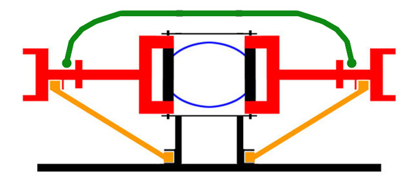
If you look at the Chevy thread there is a conversion that moves the lower inner point out and down. I'll try and find it.
Here's the web site.
Here is a pic with the relocation on a C4.

Last edited by Ralphy (2/22/2012 8:59 pm)
![]() Offline
Offline
husker wrote:
I also wonder if I couldn't move the lca inner mounting out slightly to create a little less camber change, might adversely effect handling though.
FWIW:
At the risk of being a "Modeling & Simulation Advocate," in my hobby (as well at work), I'll add, if you'd like to save a lot of time in fabrication and rebuilding - give one of the IRS/Suspension models a trial. - Reference the Software thread, there is one online - and of course, the BonesApart will let you see the results in Excel - then make your choices. "BA" will answer the camber change question, jiffy-quick.
Some of the more complete and exotic models have demo modes and include the handling analysis- but a steeper learning cure. BonesApart - is bone-easy. (not affiliated - just like the model and its simplicity)
My build has slowed to make sure I practice what I preach - the method may take a little longer - but am convinced I'll be more pleased with the results.
And, my testing will be shorter, I'll get more driving time - uninterrupted with a redo.
Cheers - Jim
![]() Offline
Offline
I didnt get carried away but did some more measuring today. I started from a 2Degree down on the axle and set the hub at O.
.875" down = 6deg on axle and + 1/2deg on hub
1.625" down = 9 deg and slightly less than +1-1/2 deg on hub
.687" up = O deg on axle and -1/2 deg on hub
1.89" up = 2deg^ on axle and less than 1/2 deg @hub
2.73" up = 6 deg on axle and 1-3/4deg @ hub
This in a 4" total movement top to bottom. And is based on the accuracy of an Ace hardware angle finder and an semi old dude with bi-focals. ![]()
 1 2 Jump to