 |
 |
 |
 |
 |
You are not logged in. Would you like to login?

![]() Offline
Offline

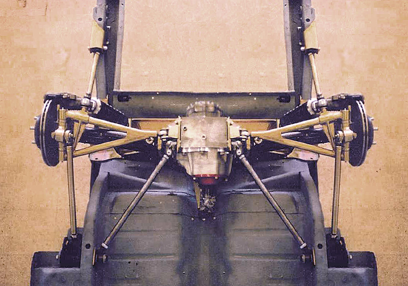
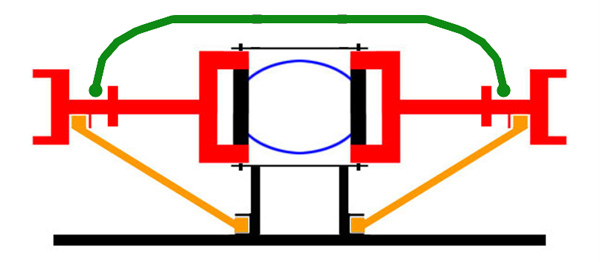
Day, it seems to me if you were to build a very wide LCA and use two coilovers per side. You may be able to get away without using any upper control. Like this one. The rear coilover would remove a lot of the twisting with regard to acceleration. Then the reverse during braking. The further outboard you would mount the coilover the better.
Last edited by Ralphy (12/27/2011 9:21 am)
![]() Offline
Offline

I am taking the opposite approach I am going to make my trailing arms solidly mounted to my wish bones (will probably make a tubular one piece unit later) and then mount my single shock, roughly in the middle of the front trailing arm pivot and the rear LAC pivot this will center the shock and help eliminate twisting.
![]() Offline
Offline
I agree with you Ralphy. I had my brother do a finite element analysis of the LCA in the hope of getting to the bottom of my wheel hop issue. He is one of Boeing's chief engineers and has full access to their incredible computers. His team of engineer's are in charge of cabin pressurization. He told me the biggest reason the Jag setup produces wheel hop is in the forged steel weldments at each end of the tube on the LCA.. The arms at the inner pivots have serious loading issues. They wag alternatingly up and down allowing the hub carrier to rotate about the approximate tube center line under heavy acceleration or braking load. The gussets I welded there do little to reduce this flex .The tube its self is more than ridged enough to resist this torsional load. The outer weldments wag some but far less due to their short length. He said the thing will theoretically twist like a springy cork screw and nearly all of this flex is the price paid for having to reach around the inboard disk brakes. He also went on to say that the LCA's are attached to the differential with only two 7/16 bolts and have insufficiently designed cast mounts to prevent the undesirable flex of all these critical pivots.. The four 5/16 bolts that vaguely hold that same casting located through a light tin plate adds to the flexing. Since the twist appears to be centered on the LCA tube, it works like staggered shocks on a live axle. Having coil overs mounted on the front and rear of the LCA will create a phenomena called a " torque couple". This would be centered roughly about the tubes center line and would tend to reduce the cyclical twist from wheel hop but not eliminate it. After he told me this I gave up on band aide solutions like the small watts link on top of the hub carrier and went to the heart of the problem. The load path from the tires to the frame is torturous and by design, weak. Once I had the leading and trailing links in place the LCA 's only function is to control toe and carry the weight. With the LCA being out of the fore and aft load path it can be greatly reduced in size and still work great in this reduced capacity. Now all fore and aft loading gets transmitted directly to the frame with no flexing through the links. I still have in board brakes and the load path is simplified and direct. No rocket science in the solution, just common sense. Klaus Arning was a sharp engineer!
![]() Offline
Offline
The image of the cobra rear set up has to be the best looking solution to the LCA problem with out redesigning the whole damn concept . The integrated "x" bracing and widened coil over mounts should provide some needed improvement . The further apart the coil overs are mounted on the LCA, The greater their ability to act as a torque couple and resist rotation while supporting the weight . Who ever did this had a good idea what forces were involved and came up with a clean design with few compromises.
![]() Offline
Offline
Tyrellracing,
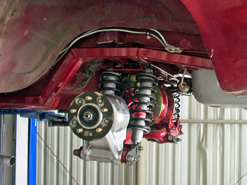
I appreciated your reply to Ralphy's thread about observing that a wider LCA and two shocks per side can produce a more stable suspension. Your brother's "finite element analyisis" sounded to be very revealing. I'm using the Jag IRS but am willing to make any modifications that are cost effective considering time and money. I plan on using a pair of differential support rods at the front and the back of the differential as well as the Watts linkage above the hubs. I'm thinking about modifing the LCA in the manner that is discussed in this thead, namely widening it and pushing the shocks outward. I mocked up a sample and would like anyone's opinion about whether or not this might improve the stability of the LCA. This tubing would be added on both sides. The shocks end up 1 1/4" outward from stock position. The tubing would be 3/4" DOM.
Photos:


Last edited by 6 speed (1/11/2012 5:05 pm)
![]() Offline
Offline

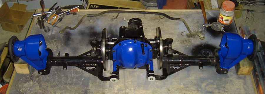
I think it would help. are you planning to just run one coilover per side??? I am approaching the same problem by putting the coil over in the front and then solidly mounting the trailing arm to the LCA and using it to effectively make the LCA a three pivot unit. Some day I may make a tubular unit and then it would look something like the arm on the left in this pic

![]() Offline
Offline
6speed:
You are on the right track. Where your tube is to be welded to the bend on the inner arm of the LCA just happens to be the weakest part of the control arm. Any reinforcement to this area will have an effect on the amount of deflection when under acceleration loads. I used two support rods made from 1 inch round tube with threaded ends for half inch heims. They are connected to brackets I made on the front leaf spring mounts and to a 1/4 plate that I used to tie the LCA inner pivot brackets I made together. This provided fore and aft as well as side to side support with only two rods. Separating the shocks further should in theory help resist the twist with their increased torque cuple. IMO. Attaching 1 x.125 wall round tubing to the inner bend the way you have shown with good quality welds will make an even greater improvement than the separation of the shocks alone. The two combined just might be a successful method of eliminating the pesky wheel hop issue with out going to the drastic measures I did. , My hub carrier is the pivot of the watts link identical to the T5 suspension in the ford IRS segment of this forum..
![]() Offline
Offline

so tyrellracing is your IRS in the car???? I know when you were posting before it was still in the works. Also how did your custom vented rotor project come out??

![]() Offline
Offline

6 speed,
I have to agree what Day said in another thread. You should keep the coilover as close to center as possible. Maybe trapping it between the original point and your new tube. If your going to use two coilovers it may not mater though.
![]() Offline
Offline
Sorry guys, I should have been more clear in my post. " This tubing would be added on both sides." meant on both sides of the one control arm, four times in total. And yes, I'll be using 2 shocks per side, four in total. (The internet is like that. You always have to be aware of how your statement might not be taken in the intended way).
I liked the theory of the widening of the two shocks on one LCA, increasing the "torque couple" effect. That's a good thing.
Also, on the later Jag IRS installations, I noticed the factory supplied a small bracket to link the outer fulcum point to the lower shock mount. This was a bolt on afair, although it seemed to me, a bracket from the inner fulcrum to the lower shock mount would have been more benificial.
This modification I've layed out here is of course entirely contained to the LCA. If I could explain the plan of my IRS installation in a bit more detail, I said I was going to use a " pair of differential support rods at the front and the back of the differential ". This would be a pair of 1" rods with a clevis at one end a nylotron bushing at the other end going, from the front inner pivot point of the LCA, angling forward and outward by 60 degrees. Theoretically, just those the two rods would be sufficient to resist the forward and aft, side to side forces of the differential. However if a little bit is good, alot must be better. Therefore, I want to add two more similar rods from the rear inner pivot point of the LCA, angling only outward by 60 degrees. All these rods would be attached to the "tie brackets" that tie the two differential side brackets or trunion mounts together, one front, one back and of course the car chassis. That's alot of hardware but I think you want to make sure the differential is in there securly. You need to put something in there to take the place of the original Jag cage.
And again, the Watts Linkage will be on top of the hub.
Getting back to "weakest part of the control arm" that inner bend, I don't see any other way to improving it other than replacing the entire LCA which is not in my cards at this point.
Ken
![]() Offline
Offline

Ken,
You mean something like this? Thread we had talked about the same.
Stablizing My Carrier
Last edited by Ralphy (1/13/2012 7:54 am)
![]() Offline
Offline
Ralphy,
You got it! And then I'll add something similiar at the front.
Looking at that photo, it makes me think about a conversation I had with Ron White from Snow White Ltd., Street Rod Parts and Mfg. He suggests the axle should be angled down at 2 degrees towards the hub on a Jag IRS installation. I asked him why and his answer was that it just works best, gives the best ride. He's been doing these installs for 35 years and this is what he's found. This 2 degrees amounts to a 1/2" difference between the differential and the axle cenre lines. Have a look at their products:
He states the 2 degree fact in the instuctions of his kits. Here's the 40 Ford instructions as an example, (you'll find the sentence towards the end in the notes):
However, in this article, you'll see they illustrated theJag IRS with the axles level:
Ken
![]() Offline
Offline

Yes! Yes! Yes!
If you angle it like so, you slow the camber curve down. I had thought about this yesterday with the bagger guys. This would also aid when you narrow an IRS. Narrowing speeds the curve! Also when you go hard on the throttle and the rear squats, the half-shafts should be close to center.
Factory I believe they want the half-shafts straight. Never below center!
Ralphy
Last edited by Ralphy (1/13/2012 9:44 am)
![]() Offline
Offline

Ralphy wrote:
Factory I believe they want the half-shafts straight. Never below center!
NO NO NO ![]()
On a factory jag setup they want the LCA parallel with the ground and in line with each other. that is where you put it when aligning the car AND is how every Jag I have ever stuck my head under looks... unless the springs are sagging ![]()
Last edited by Daze (1/13/2012 10:15 am)

![]() Offline
Offline

hay 6 speed, not to poo poo on what you are doing because I am all about making a factory part better, BUT ![]() if you are going through the effort to reinforce both sides with tubing why not just use your arms to build a fixture and then build a set of fully tubular control arms on the fixture??? just curious.
if you are going through the effort to reinforce both sides with tubing why not just use your arms to build a fixture and then build a set of fully tubular control arms on the fixture??? just curious.

![]() Offline
Offline

" Half shaft angle should be 2-3* down from center at ride height, at full curb weight.""
Russ T Nut
"I don't know where you came up with the 2-3 degree angle :confused:. The top dogbone should be level at ride height."
Chevynut
the 2-3* came from a pickup installation on a Fo*d, and I assumed it was to allow for needle bearing rotation.
Russ T Nut
**********************************************************************************************************************************
IRS Thunderbird half shaft geometry?
"There are two schools of thought about the correct setup. One being that the halfshaft should be level at max acceleration or Two that they need some angle to keeping from brinelling the race due to the high loads under max acceleration. I feel that it best to just split the max angularity that the unit will see in service. I try to put in about 1>2 degrees at steady state to allow the unit to have some plunge which increases the area that the bearings see on the race."
__________________
Best regards,
Richard Hudgins
JBL MOTORSPORTS
************************************************************************************************************************
pringles
"I was at Home Depot today and when I came out a C4 was parked behind me. I had a look under the car but it was difficult because it's so low and I didn't want to get to close to it and touch it. I am pretty sure I noticed that the half shafts are angled slightly down and the trailing links slightly up at rest. "
Last edited by Ralphy (1/13/2012 1:39 pm)
![]() Offline
Offline

I am not talking about the half shafts. I am talking about the LCA or wish bone. On a Jag the wish bone NOT THE HALF SHAFT needs to be parallel with road at normal ride height Just the way it is set in the picture posted. On the shop manual they want camber at 0º at normal ride height and they want the LCAs parallel with the road and in line with each other at normal ride height.
Last edited by Daze (1/13/2012 1:59 pm)

![]() Offline
Offline
Dog bone, wish bone....everybody's got a bone to pick!
![]() Offline
Offline

So am I to understand that this Jag view at Wiki is wrong?
Last edited by Ralphy (1/13/2012 3:41 pm)
![]() Offline
Offline
Daze wrote:
I am not talking about the half shafts. I am talking about the LCA or wish bone. On a Jag the wish bone NOT THE HALF SHAFT needs to be parallel with road at normal ride height Just the way it is set in the picture posted. On the shop manual they want camber at 0º at normal ride height and they want the LCAs parallel with the road and in line with each other at normal ride height.
Just currious - I suppose that is because at ride height - the shocks are at "mid-point""- between full bounce/jounce? Thereby giving max travel up/down on the suspension.
Cheers - Jim
![]() Offline
Offline

Ralphy wrote:
So am I to understand that this Jag view at Wiki is wrong?
yes it is and I have been trying to tell you that for months ![]()
![]()
![]() more than once you have made a comment to the effect of ' the hot rod guys make the LCA parallel to the road for looks but that not how it should be'
more than once you have made a comment to the effect of ' the hot rod guys make the LCA parallel to the road for looks but that not how it should be'
Every time I have answered back with the same response" that is the way Jag intended it". Not only is it address in the Jaguar shop manual, on the Jaguar forums, and on some of the retrofit web sites including my own, BUT every Jaguar I have stuck my head under also confirms it the LCA needs to be parallel with the road at normal ride height.
take a look at this thread that I moved from the old forum. it was originally started by tyrellracing and he Jo and I go in to great detail in to the camber curve of a Jag rear end.
Last edited by Daze (1/13/2012 4:35 pm)

![]() Offline
Offline

here is proof that the pic is both accurate and the LCAs still need to be parallel with the road. if you look at the tires they are leaning in at the top and so the camber is negative. If in the pic the camber were at 0º the LCAs would probably be parallel with the road. I am sure that pic was a snapshot from an animation and it was stopped some where in its range of motion but not at 0º camber

![]() Offline
Offline

Huh! ![]()
I never made comments of the position of the Jag IRS did I? I thought my only comment as far as Jags go, is that people like the whole look of the Jag IRS. I would also agree to that. I think the Jag is a pretty hot look.
Four coilovers are cool looking! ![]()
![]() Offline
Offline

My last comment was in reply to this.
"yes it is and I have been trying to tell you that for months more than once you have made a comment to the effect of ' the hot rod guys make the LCA parallel to the road for looks but that not how it should be' "
![]() Offline
Offline

Ralphy wrote:
My last comment was in reply to this.
"yes it is and I have been trying to tell you that for months more than once you have made a comment to the effect of ' the hot rod guys make the LCA parallel to the road for looks but that not how it should be' "
I knew that. I know we have had this conversation before, ![]()
![]() I would weed through all the post to try and find it but there is really no point
I would weed through all the post to try and find it but there is really no point ![]()

![]() Offline
Offline

I did some further looking and I am a dork ![]()
![]()
![]() it was JEM not you. It was probably someone else before him and some one else befor that as I know I have said it many times. seams to be a common misconception when installing a Jag unit that the LCAs are not to be parallel with the ground. I new I had preached this sermon before, and I thought it was to you, but I was wrong. Sorry my bad
it was JEM not you. It was probably someone else before him and some one else befor that as I know I have said it many times. seams to be a common misconception when installing a Jag unit that the LCAs are not to be parallel with the ground. I new I had preached this sermon before, and I thought it was to you, but I was wrong. Sorry my bad ![]()
![]()
![]()
![]()
![]()
![]()
Last edited by Daze (1/13/2012 4:59 pm)

![]() Offline
Offline

I'm no doubting you, conversation is more visual than we think. Lot's gets lost typing and not being in front of someone. I probably was in a different direction thinking wise. Corvette's are the way I describe down hill to flat. Then the other point I was making about narrowing I think is true. When you narrow an IRS you speed the camber curve. Imagine a half shaft 2" long and move it up or down 2". Then imagine a half shaft 10 feet long and move it up or down. The 2" length would camber all over, the 10 foot would camber very little. So if you were to narrow an IRS the first 1/2" has the least movement. By making it move through both sides of the least motion, you will slow the curve. Also lowering the inner pivot of the dogbone and or moving it out will also slow the curve. So if you narrowed even a Jag this would slow the camber.
Last edited by Ralphy (1/13/2012 5:09 pm)
![]() Offline
Offline

Ralphy wrote:
I'm no doubting you, conversation is more visual than we think.
Did you see the post above the one you just made, it was all me I am a dork ![]() Also did you see I responded to your caster question??
Also did you see I responded to your caster question??

![]() Offline
Offline

Here are the c4 camber rod re-locators.
No Problem!
Last edited by Ralphy (1/13/2012 5:16 pm)
![]() Offline
Offline

Ralphy wrote:
Then the other point I was making about narrowing I think is true. When you narrow an IRS you speed the camber curve. Imagine a half shaft 2" long and move it up or down 2". Then imagine a half shaft 10 feet long and move it up or down. The 2" length would camber all over, the 10 foot would camber very little. So if you were to narrow an IRS the first 1/2" has the least movement. By making it move through both sides of the least motion, you will slow the curve. Also lowering the inner pivot of the dogbone and or moving it out will also slow the curve. So if you narrowed even a Jag this would slow the camber.
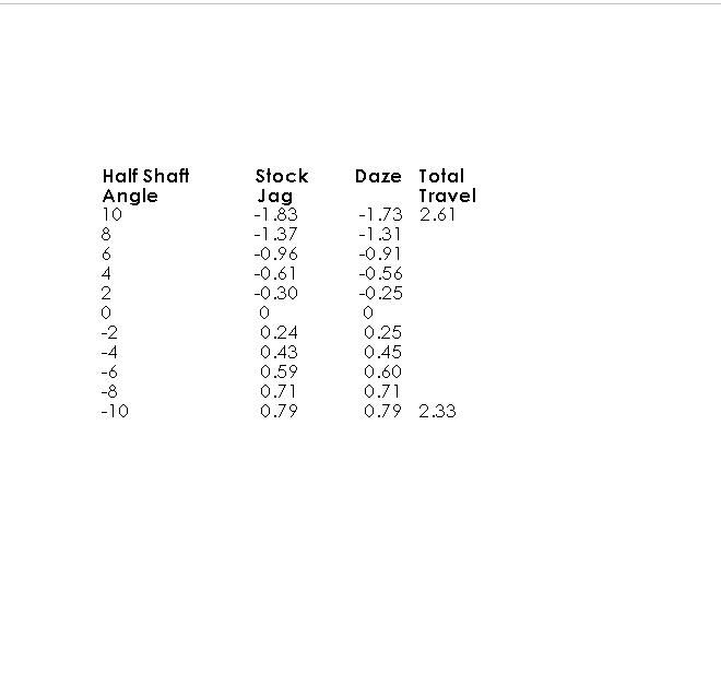
You are correct, it does reduce the curve by narrowing the parts. here are some numbers Joe ran for me comparing my narrowed IRS to a stock XJ6 unit. this is the difference 2" makes