
 |
 |
 |
 |
 |
You are not logged in. Would you like to login?
![]() Offline
Offline


![]() Offline
Offline


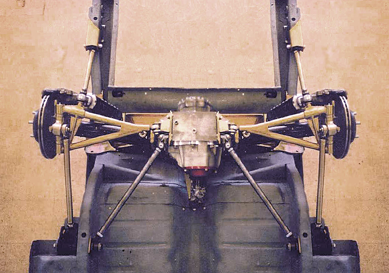
Duane Carlings T5 Early Mustang IRS
Designed by Ford engineer Klaus Arning
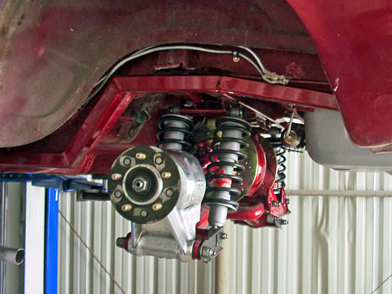
Here's another view I've had.


What kind of car is this last pic? Not a Mustang no?
Last edited by Ralphy (1/19/2014 7:32 am)
![]() Offline
Offline

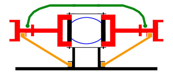
Here's a different way too do an IRS conversion.
![]() Offline
Offline

JBL AC Cobra


Last edited by Ralphy (12/30/2011 2:59 pm)
![]() Offline
Offline
For you "Horse-Holders" (just kidding 'Stang-folks):
Here is a nice looking set up --
Now, I admit this is a FRONT SUSPENSION - But it has some very nice design features worth reviewing
note the VERY short Upper Arm -- they claim no bump steer, and well designed CAD and FEA too.
They say:
-CAD/ CAM Designed and modeled using SolidWorks 2007
· Design F.E.A. (Finite Element Analysis) Confirmed using COSMOSWorks 2007
· CNC Machined out of 6061 T6 Billet Aluminum
· All geometry optimized for unsurpassed handling and performance
· Zero Bump steer
· Tested and proven on the race track
· Modular construction
· Center section of K-member removable for access to remove oil pan without need to remove engine or k-member
· Wheel track and width adjustable for race application
· 3/8" drive adjusters on control arms make alignment adjustments easy
· Spindles incorporate a 2 inch drop in ride height to maintain proper suspension geometry
· Spindles have caster already built in for better stability
· Available in traditional upright shock or cantilever pushrod design as an option for ease of tuning on track
· 3 position Adjustable anti-roll bar provides a wide range of adjustability
· Self Lubricating spherical bearings require no maintenance
· Can accommodate any caliper combination
More details here:
Its nice and modular so shipping would be easy - but I bet its not Cheap! Many of those features would be great to incorporate in any IRS.
Cheers - Jim
![]() Offline
Offline
The basic pull rod suspension layout with the blade antiroll bar has been used in F1 since the early eightys and perhapse earlier. However I have yet to see anyone use such a delicate design on a street car. The low unsprung weight would be the primary benefit and of course the cool appearance of design.
![]() Offline
Offline

Don't forget the fact that they are adjustable. So they can be fine tuned. Plus you can order different blade thicknesses. More of a racing need then street probably.
tyrellracing wrote:
The basic pull rod suspension layout with the blade antiroll bar has been used in F1 since the early eightys and perhapse earlier. However I have yet to see anyone use such a delicate design on a street car. The low unsprung weight would be the primary benefit and of course the cool appearance of design.
Last edited by Ralphy (1/05/2012 12:10 pm)
![]() Offline
Offline
In the realm of after market performance suspensions. Nearly all of them are fully adjustable. The factory original suspensions are the only ones that are minimalists as to adjust ability. The higher level performance suspension manufacturers up to and including full race suspensions are always fully adjustable. Typically the only exception to this are the suspension anchorage points because they are considered fixed points and must be robust enough to survive the rigors of hard use. In most cases having them adjustable to relocation would only weaken the design. The Griggs full race kits are so adjustable that you can adjust all the normal settings as well as adjust the axle c/l for and aft two inches, increase or decrease the track by two inches, and adjust what ever ride height with in reason you could want. The set up you found is one of the best I have ever seen that was not for F1 cars with a price tag equal to the national debt. The only reason that beautiful work of art is with in reach of mortal man is the advances in CNC machining. Thirty years ago the available machine technology would have made that product too expensive for anyone to afford!!! Fast forward to today, the CAD software combined with CNC machine software and tools have made the highest technology that only the aerospace industry had available to everyone. Once the product is designed, programs are written and the fixtures are in place, you only need unskilled employees to feed raw billet into the machines. In recent years Machine tool technology has gone ballistic and we are all riding the wave of affordable technology!! I phones, P.C. ect!
![]() Offline
Offline
The only reason that beautiful work of art is with in reach of mortal man is the advances in CNC machining. Thirty years ago the available machine technology would have made that product too expensive for anyone to afford!!! Fast forward to today, the CAD software combined with CNC machine software and tools have made the highest technology that only the aerospace industry had available to everyone. Once the product is designed, programs are written and the fixtures are in place, you only need unskilled employees to feed raw billet into the machines. In recent years Machine tool technology has gone ballistic and we are all riding the wave of affordable technology!! I phones, P.C. ect!
I'll second that!
30 years ago it was trash-80 computers and my first IBM-pc had a whopping 256k onboard memory! Dual disk drives (singlesided) were the same. But you could expand (adjust) with time. A smart move on BMs part.
COmputing was left largely to klunky wordstar and supercalc. They cost about what MS Office does today - and the machininig opportunities have kep the pace too. Though relatively expensive CAD is affordable - and many of the CAD designers have the CAM packages as well. For several years I have "hobbied" in the CNC areas - but have not moved close enoughto milling metals - strictly foams and timber the occasional plastics. All set aside now for the IRS-addiction.
The garage machininst has within their reach much of the capability that was formerly held only by major industry.
There are some simple adjustable mounts that can be used "track-side"that require only simple welding to install. [Simple welding - something yet to be defined ![]() ]
]
Cheers - Jim
![]() Offline
Offline
Interesting how the designer chose to use such a short upper control arm in relation to the lower c-arm length. This set up would provide way too much negative camber gain with any more wheel travel than maybe 2 inches. It 'does not appear to have any anti-dive geometry built in either. IMO.. This would provide the best results when wheel travel is reduced to near zero. When not in use? All in good humor! Its pretty to look at.
![]() Offline
Offline

tyrellracing,
Good catch on both points, the zero anti dive goes along with the Deigned To Bind thread I posted.
![]() Offline
Offline

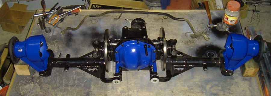
Hurricane Motorsports Ford 8.8
![]() Offline
Offline

Factory Five Cobra IRS
Last edited by Ralphy (1/09/2012 10:29 pm)
![]() Offline
Offline

Ford IRS history, lots of good reading.
Last edited by Ralphy (1/09/2012 10:58 pm)
![]() Offline
Offline
I have always liked the Factory five product line. IMO. The entire concept of using a 5.0 Mustang and, adding their kit to produce one bad ass affordable GO TOY is genius in form and function!!!!
The mustang and Thunderbird IRS is a decent design once the compliance of their too soft bushings have been removed. The big drawback to installing these in early mustangs is the upper control arms interfere with the frame rails. The solution most people use is to "C" notch the frame where the UCA's interfere. IMO the correct solution is not to simply remove some frame and cover the hole but to maintain the frames cross sectional area and move the frame above the floor in the area where the UCA would interfere. Most "C" notch jobs I have seen were done wrong. The result of the"C" notch is reduced torsional stiffness in that general area . The reason the Jag IRS works so sweet in so many applications is the design uses no upper control arms. I see that as a plus not a minus.
Years ago I got a book called CHASSIS ENGINEERING by Herb Adams. The author described the Jag IRS as suffering from camber control and deflection steer problems that were the result of any looseness in the LCA's. I think the guy was ignorant because all IRS setups suffer from those problems when they have looseness in the LCA.
![]() Offline
Offline
I'll add a downside to the Jag, and the C3/4 Corvette, and any IRS using the half shaft as a loaded component.
Single point failure = disaster. Shear a half-shaft and you're off piste! (That's ski-trail speak - not the other thing - spelling and word order is different.)
There is a company that has designed a safety upper link - that integrates a safety loop - DragVette. I'll post in the aftermarket section.
Cheers - Jim
![]() Offline
Offline

TR,
I have that book and I have read that. But he does elude to the point that PJ makes. He does also mention the Corvette C2, C3 as being inferior. Also what I remember seeing is not the frame notched, but the UCA having a C shape to clear interference. Like this Heidts.
About the Drag Vette setup PJ. They (Steve Yates) removes all the camber with that setup so the tires stay flat on the pavement during a hard launch that a drag racer needs. For most this is not desirable. He susgests also, zero camber is better for corner carving. Which I'd have to throw the BS card on! Watch the video below.
Last edited by Ralphy (1/10/2012 8:45 am)
![]() Offline
Offline

Lincoln Mark VIII Bagged IRS
Last edited by Ralphy (1/10/2012 10:30 am)
![]() Offline
Offline
Ralphy:
They did a write up in Hot Rod mag a while back where a supplier of kits for the t-bird irs to early mustang installation did just that. Cut large segments out of the frame then simply welded sheet metal of the same gauge over the hole. The UCA cannot be "u" shaped far enough to give an acceptable ride height because the upper pivot is too close to the frame for that to be effective. At least that is how I remember seeing it.
I know I have the magazine and wanted to find the old article so I could more specific but so far cannot. I also have seen this done in images on line. Its nothing new just poor fabrication technique. BTW Awesome downloads on Klaus Arning and fords suspension computer. I enjoyed all the different images you have compiled on the variety of IRS designs out there. This stuff stirs my creative juices and even though its midnight, I have this urge to go out to my shop and weld on something!
![]() Offline
Offline
I am pretty sure the mystery IRS is a Toyota Supra. Who knows what they are putting it under. The inner 6 bolt sliding three lobe CV's are classic Toyota parts. They are common on the Supra IRS, IFS 4-runners and IFS P-up's with 4x4 package
![]() Offline
Offline
Ralphy: in response to something that had nothing to do with me
The school of thought on reducing the camber to zero for cornering has to do with the ultra low profile tire technology. If you can keep the car from leaning and the bushings from distorting, from lateral g loads the wheel should remain perpendicular to the road surface. Ultra low profile tires do not suffer from sidewall roll over so a negative camber gain will actually decrease the tread contact patch while under cornering load. IMO it sounds like a steaming pile of BS theory, but I read about in Car and Driver for what that's worth.
Last edited by tyrellracing (1/11/2012 2:07 am)
![]() Offline
Offline

So TR, are you saying tire patch was compromised from weak bushings? Also if you get no roll you get no camber.
Last edited by Ralphy (1/11/2012 4:56 pm)
![]() Offline
Offline

Installing a 99+ Cobra IRS into a Fox Body
![]() Offline
Offline
Ralphy:
Not exactly, soft bushings can allow the alignment to change under cornering loads. Usually they will allow lots of positive camber on the outside front tire. This is the recipe for under steer and a poor handling car. Combine this with tires that roll over and you are driving on the sidewalls when lateral forces are present. Now the point of the article I read was If the car does not lean in a corner and the caster does not change due to bushing deflection when cornering the tires should remain as perpendicular to the road surface as they would be when stationary. This will give the tire the greatest possible tread contact patch provided the tire does not roll over under cornering loads. Ultra low profile tires do not roll over from cornering forces. There fore If the wheel is not pushed into a positive camber gain from cornering loads no preset negative camber will be required to maintain full tread contact. I hope that makes sense to you.
![]() Offline
Offline
Ralphy wrote:
Lincoln Mark VIII Bagged IRS
That appears to use the Thunderbird/Mark VIII uprights (so does the Factory Five rear and the Hurricane one pictured) and diff pumpkin but all the rest is fabricated. Maybe they borrowed some of the geometry but, given the layout of that upper arm, I'm betting it's not too similar.
Last edited by JEM (1/14/2012 10:40 pm)
![]() Offline
Offline

Here is the page on bump steer. Titled,IRS Bumpsteer
"At 2" of bump travel, the factory roll-understeer and bumpsteer were considerable - roughly 0.35 degrees of toe change at each wheel"
David does get a little crossed up in his explanation, here he contradicts what he had said previously. "(i.e., toe-in at the inside wheel and toe-out at the outside rear wheel)"
Then here he talks, adding over-steer when in fact his new numbers show a more toe neutral IRS. Which is what he does want. "The new toe-curve provides 'roll-oversteer' at the rear of the car."


Last edited by Ralphy (1/23/2012 6:08 am)
![]() Offline
Offline
The real impact of rear roll-oversteer is what it does to the steering, and any significant amount of rear roll-oversteer is going to make the car twitchy.
![]() Offline
Offline

If you like what you see with this T Bird IRS with a dummy C3 QC cover, follow the thread link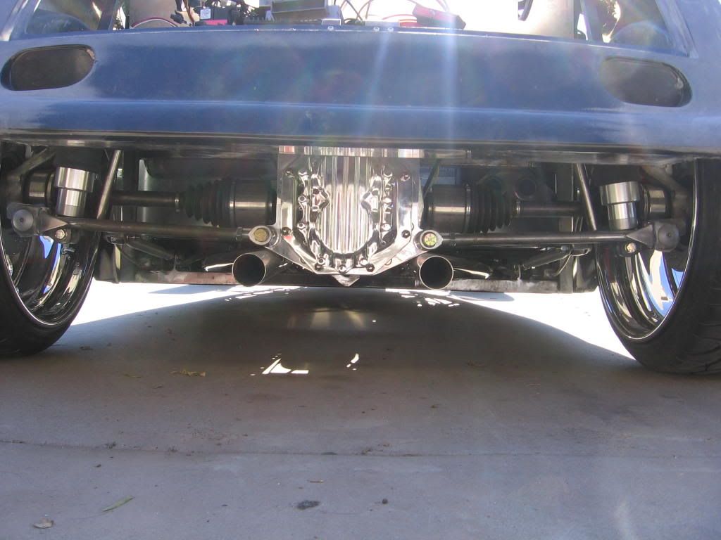
![]() Offline
Offline

Need a place to just park this link for a bit.
![]() Offline
Offline

Here is another version of I guess the T Bird IRS. Notice how FasterPatrick lowered the LCA. Then also dropped the coilover even lower inside the LCA. Seems to me this makes for a strong setup.
Ralphy
Last edited by Ralphy (2/27/2012 6:18 am)