
 |
 |
 |
 |
 |
You are not logged in. Would you like to login?
![]() Offline
Offline

Uh Oh,
Your getting the disease. Once you start seeing things you start seeing things day and night. LOL!
Last edited by Ralphy (11/21/2011 7:33 pm)
![]() Offline
Offline

Mongoose930 wrote:
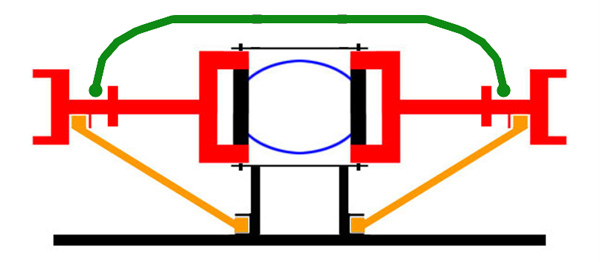
That makes perfect sense. Now that I look at your signature drawing, I see exactly how the arc is removed when the suspension travels in the vertical plane. I take it these are usually fabricated or does someone sell brackets, bushings, rods, etc?
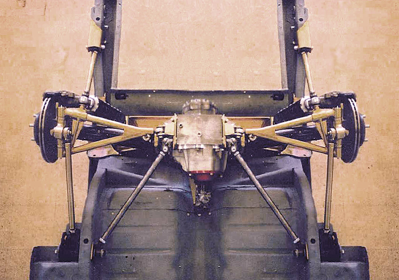
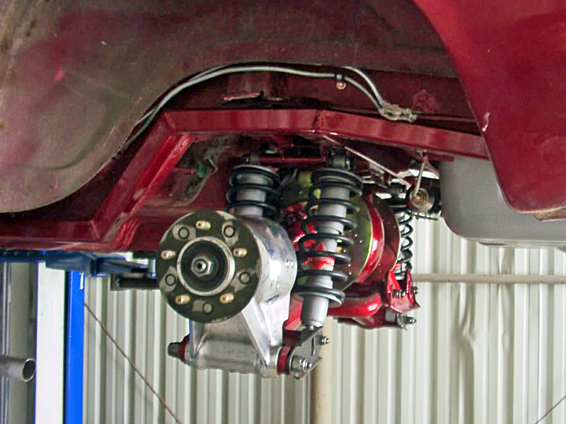
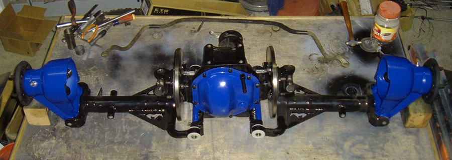
Ever car and application is just a little different so this is a situation where some custom fab work will need to be done. Nick should be able to help you if you are not set up to to it your self. Here are some different pix of the ways people have set it up


![]() Offline
Offline

Am I seeing this right? Is one inner pivot point longer than the other? Front left of pic.
Toe steer? If so, the longer would go to the rear. And they would have to be mounted with heims?
Last edited by Ralphy (11/22/2011 9:17 am)
![]() Offline
Offline

I think it is an optical illusion, but it is hard to tell for sure on that pic

![]() Offline
Offline

I think your right, I don't think it would pivot. Heim or no heim.
![]() Offline
Offline
Thanks for posting these pictures. It looks like a couple of these designs do not remove the arc of the trailing arm which I think would pull the hubs forward as the suspension travels up and down.
Nick has been doing a lot with tubular suspension pieces so I am sure when I am ready to kick off this project, he will be able to fabricate everything I need. The rear suspension on his Cobra is a work of art and absolutely true to the original design.
![]() Offline
Offline
I hope you guys can forgive my ignorance here, but what are the trailing arms actually accomplishing other than adding rigidity to the LCA where they are angled back to the linear pivot point of the lower fulcrum? On the shiny tubular set up the center section is braced back up to the frame\front Xmember. The design of the LCA would look like it should take any torque on its own. What Im wondering is if on the Jag set up it could be compacted by utilizing a beefier "skid Plate" and making it more of a working piece by running LCA support back to it just infront of the LCA mount and also anchoring to the frame from near that point. I probably don't have my terminology right on some of this. Hope this doesnt sound like jibberish....
![]() Offline
Offline

Yes the wishbone is beefy and there is not a lot of flex in it, but It is all about levorage. by the time you get to the end of the wishbone there is a lot of leverage flexing the the pivot points. The biggest issue is not so much flex but rather deflection. as forces are applied to the arms in a for and aft motion it can deflect in to wheel hop. The two times the trailing arm is truly important is during braking and acceleration.

![]() Offline
Offline

Day,
I go over my design ideas mentally and then I see Heidts design. I posted about strengthening my carrier mounts and then again view Heidts setup. Look at limited mounting? Look at the LCA's? The whole thing looks very light. guess I am trying to over build? Hmmmm.........
![]() Offline
Offline
Thanks for the input Daze. This is kind of where my mind is going. Just making it part of the skid instead of the forward framework that I dont think I will be able to incorparate. Im working with straight frame rails Above everything and want to keep the clutter to a minimum seeing as this thing isnt going to be set low to the ground.
Ralphy, I have a tendacy to overkill terribly, probably from the size of the stuff im used to working with. Having a lot of fun thinking this stuff thru !
Last edited by Digz (11/24/2011 5:24 am)
![]() Offline
Offline

I don't think that is the best option because the Jack plate/aignment plate is only held by the diff. You really need to tie it in to the frame somewhere in addition to the jack plate. in the case of my car I tied it in to the pinion support. In the following pic the arms are not installed but the front pivot for them is.
as to overkill, unless you are an engineer that is the only way to do it.
