
 |
 |
 |
 |
 |
You are not logged in. Would you like to login?
 1 of 1
![]() Offline
Offline

on August 12, 2010, 1:23 pm, Daze wrote:
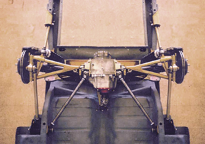
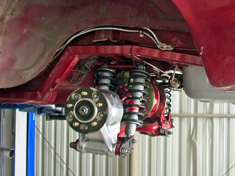
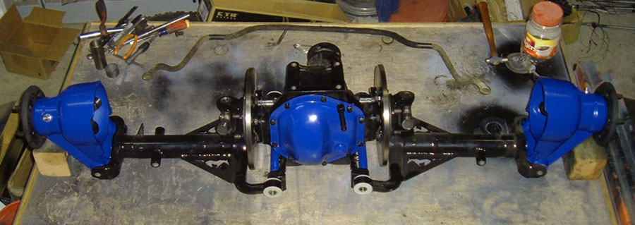
I look through all the info Ralphy posted, especially the cobra thread about the watts link at the hub and have condensed it here with pictures so that you can look it over and give your opinions. Any thing I add will be plane text, but quots from the other forum will be bold and itallic.
These first two pictures are the watts link setup that inspired the thread.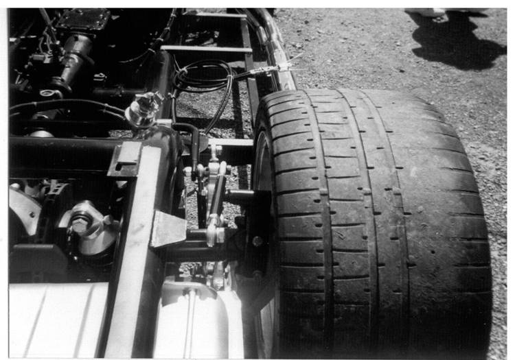
This is the bracket designed to bolt to a stock hub for the watts link mount
here is the bracket bolted to the hub
And here is the actual wats link in the car
[img][/img ]
this one is the same basic design except it has a hub speciffically designed for watts link instead of modifying the original Jag pieces
on the Cobra forum mickmate wrote:
on the Cobra forum lal Ninja wrote:
What are the advantates/disadvantages between the Watts design versus the design shown in the photos below?
Another question. Should bot both systems Watts and the linkage shown in the photos be used?
lal Naja
The watts stops the carrier trying to twist around the axle. The lower radius rods stop the forward back movement down at the bottom by the lower arm. You have a good point, if both were on the car it would be about the ultimate set up on these rear ends.
mickmateThis is a link to video of mickmate's watts link in action
on the Cobra forum mickmate wrote:
on the Cobra forum PDUB wrote:
Nick, Are you sure that the Jag hub carriers are capable of handling the stress associated with carrying this newloading? I'm not saying they won't take the punishment, just wondering about it.
PDUBGood question the top is a conical shape very sound casting with 3/8 wall. The bolts are screwed into steel inserts in that. I'll be testing it confidently ;-)
mickmateI found this entire thread very fastenating and you may want to read through the whole thing, but based on the info I have posted here what are your opinions??
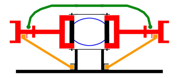
Also here is a link to another forum that gives the basics on a watts link. this set up is being used in a live axle but the info still applies.
![]() Offline
Offline

on August 12, 2010, 2:19 pm, Mustsed wrote:
I am still in the opinion that the watts linkage shown in the upper .........pictures is a good idea but misplaced. The part in a Jag rear end which is in an fore/aft movement is the wishbones and the watts should be placed there. Mounting it higher up is just adding leverage and more moving parts therefore like hub to wishbone bearings and also the wishbone to differential bearings.
I will try to make a temporary mock up of my idea and post a pic of it until Saturday.
In my opinion the second system is better if chosen from the two given ones. It gives a solid wishbone which in the end doesn't try to move the complete rear end in a hard brake or launch situation.
Hope the above is somewhat understandable.
Mustsed

![]() Offline
Offline

on August 12, 2010, 2:53 pm, Ralphy wrote:
Direction of force Mustsed I think I understand you. Your saying the direction of force on the wishbone is horizontal, which I think is somewhat true. However you have a basic triangle with the center of the wheel the top of this triangle. Under hard throttle force is pulling from the center, hub bearing area. Like a lever I think this is twisting the wishbone, pulling up on the rear and pushing down the front. Stabalizing yur carrier at the top (watts link). Removes this rotational force and now only burdens the wishbone pulling forward. At this point I think the wishbone would be up to task. My question would be once the watts is set, wheels aligned and all. A year later you need to realign, would the watts be out of place. I am also thinking that where the watts mounts to the frame to have a slotted hole for lateral movement.
on August 12, 2010, 4:57 pm, Ralphy wrote:
Here is another approach
Make my Jag rear stronger? Help-Ideas-Advice


on August 13, 2010, 12:16 am, Ralphy wrote:
Watts running fore and aft Daze as I originally told ya, I have searched IRS ideas pretty hard.
Here's a watts running front to back. Wisbone dogbone? I guess dogbone would be correct!
Last edited by Daze (10/27/2011 3:48 pm)

![]() Offline
Offline

on August 13, 2010, 8:38 am, Daze wrote:
I believe that is exactly what Mustsed wants to do he is going to eat this picture up. Thanks for all the posts!!! Like I said in one of my other posts, I have done tons of research for this project, but other than that one link from ERA replicas, I had not seen any of links you have provided. lots of good food for thought.

![]() Offline
Offline

on August 13, 2010, 9:27 am, Mustsed wrote:
That is what I tought of when talking about watts linkage ! Absolutely the system I had in my mind.
So what are the toughs about this one. Would like to hear the experts suggestions!
Mustsed

![]() Offline
Offline

on August 13, 2010, 9:38 am, Ralphy wrote:
Cobra Kits #1 User Of Jag Rear Mustsed, you can contact the guy at Club Cobra and ask the whys. I notice the front link is not parallel with the rear it seems. He has a couple of mounting points. This will cause some movement in the dog-bone. Also if you read the thread, some come to the consensus that using both watts would be the hot setup.
Ralphy

![]() Offline
Offline

on August 13, 2010, 10:55 am, Daze wrote:
Found another picture with the pivot side
on August 13, 2010, 5:07 pm, Daze wrote:
Mustsed, I think you may have me convinced I may go watts rather than my previous trailing arm idea. I like the fact that it is solid in both a push and a pull configuration and the lack of bind in vertical travel. Also I think that system could shave a few pounds over what I had planned.
Last edited by Daze (10/27/2011 3:51 pm)

![]() Offline
Offline

on August 13, 2010, 11:30 pm, Mustsed wrote:
I don't understand why the system in the pics has......... the trailing arm ear on the lower arm slotted (at least it looks like it is). It might be easier to fit the equalizer bolt in there w/o the need to remove the shock but isn't that against the rigidity of the mount?
The only thing that is holding me from starting my install is the incredible heat over here above 44 degree Celsius. Not funny to work in a sauna when you can't see what you are doing because of the tears in your eye's.
Mustsed

![]() Offline
Offline

on August 14, 2010, 11:50 am, Ralphy wrote:
I'm sure you noticed in the watts link image the guy is running a single coilover. But look at which side he has put it. Then think what happens under hard load. This will only add to the twisting unless you are running a upper watts. This brings me to another point, running an upper watts means you can run one shock and one coil. I find the double coilover to look oh so cool, but why? How in the world I still wonder do you balance the load from the front spring to the rear? Then can you match right with left? Too fricken confusing!
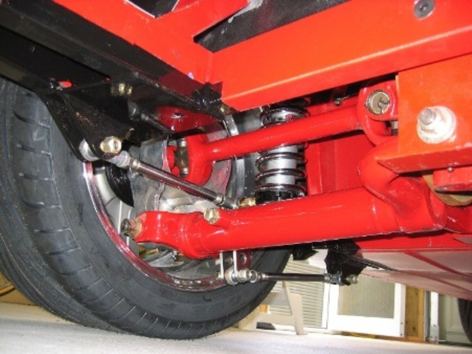
A-arm lower watts link on top and one coilover up front. That's the hot setup I think.
on August 14, 2010, 12:49 pm, Ralphy wrote:
Why Is A Guy With A Corvette IRS Here? I have a C3 style IRS that needs change. They guy that installed the unit cut into the rear firewall and my forward control arms are inside the passenger area!
So what to do, I have been toying with two ideas. Go to a Guldstrand type of setup or could I mimic something similar to a Jag? What I do not like about the Guldstrand coilover is that it mounts the lower end of the shock to the bearing carrier. This to me seems it will only force the halfshafts inward putting more strain on the center section. If I build a new bearing carrier and lower A-arm I can mount the coilover to the A-arm and that I like. Please look and tell me, do you think it would work?
The below link is what I have. If I remove the lower single camber rod and build an A-arm. Then add an upper watts link and the shock would stay in about the same place as in the link. Except I will have to bring the top mounts in app. 4" inside the frame. One other thing is that my half shafts are narrowed app. 1". Plus Chevy built two lengths,widths of the C3 and I have one 1" less of the shortest. So the unit in the link my be 4 plus inches wider.
Ralphy
Last edited by Daze (10/27/2011 3:56 pm)

![]() Offline
Offline

on August 14, 2010, 10:07 pm, Daze wrote:
First of all you are here because you have an IRS rear end
just because you are the only... one not running a Jag rear doesn't make you less welcome. in fact I would love it if we had more diversity. I think there are good and bad things to all the OEM IRS units and the more diversity we can get the better we can build our systems. You have been a huge benefit to this forum, and I have to preach about it not being a Jag rear forum because I want the diversity
Now to much more important things like suspension geometry and such Is this an actual picture of your cars IRS?
As to the first thought the Guldstrand setup looks sharp, although I wonder about the rigidity in the LCAs being that they are a two pieces. what kind of $$ is that system?? If you built your own LCA with a custom mount, that would make for a better system, but at that point you are so close to a Jag rear, why not go that way???
I think your second option is a better one. you are kind of taking the best of both worlds.
I personally am leaning toward a watts system with my Jag install. I was going to do a trailing arm like this
but after seeing the watts link in that picture I think that may be the way to go. I am undecided on the upper watts. I can see the benefit, but I wonder how much wrap there actually is, I know the Jag V12 put out a lot of power and I don't think it had a problem breaking hubs or with excessive wheel hop. with that said more control and planting the power to the road is always a good thing, so I am intrigued.

![]() Offline
Offline

on August 14, 2010, 10:37 pm, Ralphy wrote:
Pics!


You can see where he cut into the rear firewall.
Has a 428 FE plus .03 mild cam and an Edelbrock intake, 4 speed top loader and a Corvette C3 rear with 3.36 gears. Mustang II front suspension. Emissions include a PCV valve and that's it!
Last edited by Daze (10/27/2011 4:09 pm)

![]() Offline
Offline

on August 16, 2010, 9:15 am, Daze wrote:
Thanks for posting the pictures. Aren't those holes... in the rear fire wall there for ventilation Its a tight fit, but that vett rear end looks good in there. you have enough room to upgrade the suspension??
As an aside if you use the "direct" address rather than the "forum" address the pictures will post full size directly in the post,rather then thumbnails that direct us to imageshack.
Thanks again for th posting the pics

![]() Offline
Offline

on August 16, 2010, 4:46 am, tyrellracing wrote:
I believe the set up with the watts linkage shown was a race set up and adjustments are checked or made before every race. It looks like one hell of a good set up as long as you dont mind the probable maintenance required. I think I feel a case of plagiarism about to occur. The anchor points may be tough to build into the mustang frame rails but I love the simplicity of the design. I an curious how well this setup combats wheel hop?

![]() Offline
Offline

on August 16, 2010, 8:49 am, Daze wrote:
hey tyrell, if you make a sub frame like I did... the anchor points will be a piece of cake What did you think of my idea to use the XJ40 - X308 hubs as a way to use factory mounts??

![]() Offline
Offline

on August 16, 2010, 11:55 pm, tyrellracing wrote:
The out board brake hub carrier would be the way to go for sure. The reinforcement provided for the brake caliper would be more than adequate to mount the center linkage of a watts link. My only reservation would be that since the LCA when viewed from the side moves at an angle and not vertical. The anchorage points would have to be at that same angle but 90 degrees removed. (perpendicular) Any error in this would make the suspension bind and eventually fail. I feel the top mount watts set up goes further to solve the twist of the LCA generated wheel hop issue than the lower mount lay out. Using the trailing arm mount for the watts link would provide no more stability than the arm it replaced. When they slotted the ear in the posted image of the lower link layout I believe they broke the set ups back for the ease of assembly. The movement of the LCA is sum what minimal in the fore and aft direction under load. However this small amount of deflection can create large problem if allowed to cycle. aka wheel hop. With this in mind, there can be virtually zero free play in this linkage for it to be effective. This is why I feel the slotted ear used for the mount made the linkage pointless.

![]() Offline
Offline

on August 16, 2010, 9:02 am, Daze wrote:
I got to thinking about it, I don't really see any adjustments in the design, so... what would need to be adjusted??

![]() Offline
Offline

on August 22, 2010, 9:06 pm, Ralphy wrote:
I would think this here is a simple way to reduce your forward twisting Mustsed. Seems to me I would rather stiffen something with no moving parts!

 1 of 1