
|
|
|
 |
 |
 |
You are not logged in. Would you like to login?
![]() Offline
Offline

Tell me where I'm wrong here. Any time you add an outboard link such as trailing arms or links. Or you design in anti squat/dive in your IRS. Your adding a bind into your suspension. Throttling out of a turn or braking into, it either pushes or pulls on the chassis. In the case of trailing arms this pushing and pulling comes from the worst place, at about the outermost point from center. This in effect causes a spring rate change that varies depending on how much brake or throttle you add varies the effect. Which can be considered a bind. Yes the ideal forces should be centered at the carrier! I'll say it again, the double wishbone is the answer. With horizontal control arms this ensures minimal effects on the chassis. allowing the tuner his or her best chance of dialing in.
The Jaguar design is half way there if you remove any fore and aft links. However now you end up with a to flexible set up. So you say add a Watts link up above. But does this now add binding back into your design? Would it be crucial to keep the Watts link also horizontal at it's static position. I'm thinking that to take a Jag IRS and making a new LCA and adding a Watts link will give the closest thing to a double wishbone.
Lister Storm designer's top ten list of importance puts installation stiffness as number one on his list.
Ralphy
Last edited by Ralphy (1/05/2012 6:36 pm)
![]() Offline
Offline
Ralphy -
You've touched part of the problem I think. The binding.
Another problem is Geometry Change - 2nd order effects - from those IRS components/elements & the binding you reference.
The Corvette C3 single rear trailing arm - or any dual trailing arm is going to be in the similar outermosts position on the axle. As they move through their range of motion - the forces on the hub will certainly change the camber, caster, and resulting contact patch. If it binds erratic discontinious motion jerking may be experienced - resulting in a vehicle that may be "twitchy." Compound those changes with a track surface ruts, bumps, other vehicles - and the ride may be "off course."
Using a pushrod to a torsion bar may transfer some of the forces and motion inboard, and reduce the binding at the hub, but the bars influence on the IRS set up also reduced - calling for larger/stiffer = heavier, to get the same chassis rigidity. That additional weight is nearly wholely sprung - a good thing. The pushrod unsprung - light by comparison.
Sounds like you are looking for a double wishbone - adjustable link set up?
I know my engineering and execution will require much adjustment - so am oplanning those bits in. It all adds up and like Listers List - for now the cost factor in the bottom half: (His list in order - My edits are the numbers in brackets)
Installation stiffness, [4 - again added after the geometry is fixed and minimize its effects on the higher priority items]
Car packaging (aerodynamics, chassis structure and regulation requirements) [5 Stiffen chassis, add aero improvements]
Cg height [3 - I can influnce marginally with a modificaton to my 'vette - small amounts - but useful]
Unsprung weight [10 - wheels and tires are killer]
Cooling (brakes and bearings). [9 - actually I'll include in the Aero]
Other, secondary, priorities include – in no particular order:
Cost [6 NOTE; I add Time to this and would call it RESOURCES - maybe include the Design resources here too]
Ergonomics [7 - Hey its a racecar!]
Design resources [8]
Motion ratio [2 - this is driven by the geometry]
Geometry [1 My main focus - once its settled al that is left is adjustments]
The sooner I can exit the DESIGN SPIRAL - the sooner I can cut metal and get on with it!
Cheers - Jim
![]() Offline
Offline
I always understood that in order to create anti-squat on a IRS the wheel travel when viewed from the side could not be perpendicular to the road surface. It had to be angled so that as the tire went down it would move forward and as it went up it would move to the rear. This is the reason the Jag irs has its lower control arms angled to produce this effect. The Jag is a linear example. The Klaus Arnold design uses a watts like linkage to produce an exponential curve wheel travel that is far superior to the Jag's system. The reason why is when the suspension is at a constant angle the thrust from acceleration will lift the rear of the car past normal ride height allowing the wheel to move forward in a continuous rate in relation to the vehicle. By contrast on the K.A. setup the wheel travel is a curve that when the rear is above normal ride height it travels near vertical. However when the wheel is compressed below normal ride height it's travel curves to the rear at a steeper angle with each inch of compression. This gives the rear greater leverage to resist squat the harder the car is accelerated but that leverage tapers to zero as the rear reaches normal ride height. In a nut shell, Correctly applied antisquat will hold up the rear under acceleration but never lift the rear above normal ride height. Pumping the suspension up past normal ride height will start the most dangerous type of wheel hop cycling. As the thrust propels the rear of the car up too high , traction will be lost, anti-squat geometry will be defeated and the rear will drop starting the cycle all over again.
Last edited by tyrellracing (1/06/2012 6:54 pm)
![]() Offline
Offline
All is true. However you have to first decide how the car is to be used. For street application or drag racing maybe, the anti squat is a usable feature. But for say road racing or just pure street performance cornering ,anti squat creates a varied effect on suspension load rates at each wheel. Depending on just how much acceleration or braking is used in each (turn) individual situation. In order to tune a suspension for high speed cornering, consistency from a neutral design, creates a more easily tuned chassis. With the more modern designed dual wishbone you can add anti squat, however the force is transferred from the wheel to the chassis from the inboard point of the control arms. Closer to the center line of the chassis. This allows for a more consistent spring rate at any wheel corner.
Ralphy
![]() Offline
Offline
Ralphy. When I first installed the XJ6 Jag Irs in my mustang , I knew that it had a large amount of anti-squat built into the design. I set the pinion angle parallel to the crank shaft c/l and figured the anti squat couldn't hurt. The shocks that came with the rear were factory type units that had little dampening on compression and less on rebound. The engine in my car is a 408 Stroker Cleveland and its a torquey "I used a word I shouldn't have". On the first outing with the new suspension I started testing it gently and progressively pushed it harder and harder as my confidence grew. I spent the majority of the shakedown run going around bumpy corners hard. I was absolutely impressed with the improved ability to hold traction on corners that the live axle would not have. Up til then I was gentle with my acceleration so I down shifted at 45-50 mph to third and cracked open the secondary's. This would normally have made the car take off like a rocket. This time the rear of the car rose up 3-4 inches and the rear wheels hopped so bad I was sure I had broke something. This was not a standing start nor did I drop the clutch violently. I simply down shifted a gear and gave it 3/4 throttle. The type of anti squat designed into the Jag rear is IMO, very torque sensitive. My first solution was to make new LCA mounting brackets with a greatly reduced angle and subsequent anti squat. The problem was reduced but remained. I purchased new AFCO shocks and changed the valving for max dampening on rebound I had a pair of heavier rate springs so I installed them. Each change helped to reduce hop and improved the cornering grip but none of them solved the wheel hop entirely. The Arning type hub carrier and linkage finally did that.
![]() Offline
Offline
I would love to see some pics. Can you post some shots here?
Phantomjock I'm sure has read on Vettemod of the guy removing almost all his anti dive on the front f his Corvette. He reports better control.
Last edited by Ralphy (1/07/2012 12:17 pm)
![]() Offline
Offline
tyrellracing,
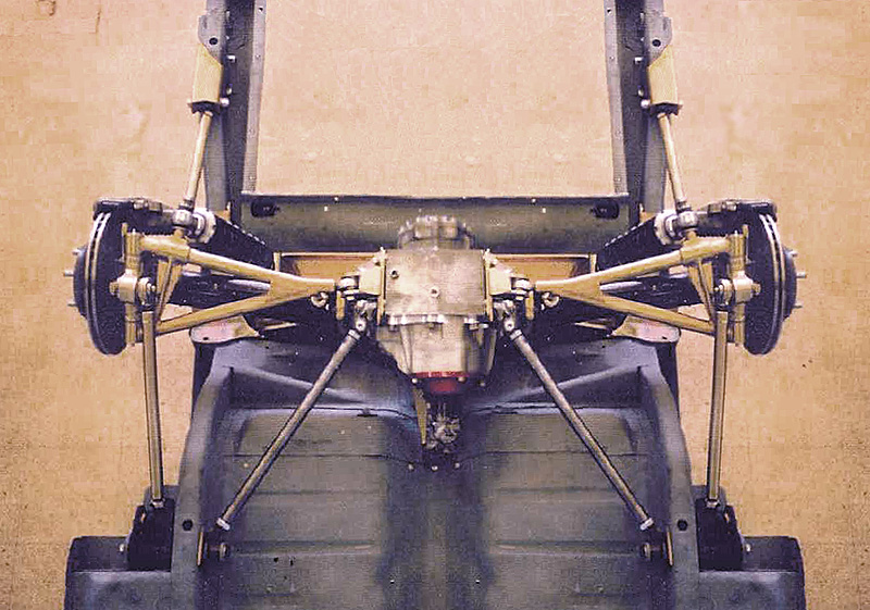
This picture bellow is of the exact frame design I have. Builder added the rearward mount to the frame. This is where I first sought out the Watts link design. Then I saw the Klaus Arning design. I still wonder if this would create to much anti squat? Seems the rearward link would maybe cause a large amount of anti squat, no? Can you explain exactly at what position your fore and aft links are? Or post some pics? You can also understand why I am wanting to keep my coilover forward, the rigidity of this chassis is not the greatest.
Picture is from Club Cobra, it's of a Everett Morrison AC Cobra chassis.
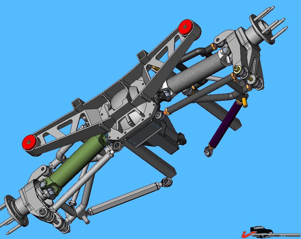
Here is Klaus Arnings design. The first pic at the header here is a lower view of the same design.
Ralphy
Last edited by Ralphy (1/09/2012 7:23 am)
![]() Offline
Offline
tyrellracing wrote:
... Up til then I was gentle with my acceleration so I down shifted at 45-50 mph to third and cracked open the secondary's. This would normally have made the car take off like a rocket. This time the rear of the car rose up 3-4 inches and the rear wheels hopped so bad I was sure I had broke something. This was not a standing start nor did I drop the clutch violently. I simply down shifted a gear and gave it 3/4 throttle. The type of anti squat designed into the Jag rear is IMO, very torque sensitive. My first solution was to make new LCA mounting brackets with a greatly reduced angle and subsequent anti squat. The problem was reduced but remained. I purchased new AFCO shocks and changed the valving for max dampening on rebound I had a pair of heavier rate springs so I installed them. Each change helped to reduce hop and improved the cornering grip but none of them solved the wheel hop entirely. The Arning type hub carrier and linkage finally did that.
That is an interesting story - and surprisinmgly enough - I spent my lunch hour talking with Mark Savitske. He was mentioning a similar situation with another vehicle. With this one, again revalving/reshock was so go. They could just crack the throttle then at 65 and 'smoke-em' Mind you 850BHP ath te wheels - but such an interesting coincidence. This was a former Drag Car they were bring up to all-around Pro-Touring and amazingly - their 60ft times were better too.
Got Lotto Numbers to pick?!
But, its making me think - for my IRS - and outboard brakes - for starters - I'll set zero anti-squat.
Cheers - Jim
![]() Offline
Offline
PJ,
Klaus Arning built a design also for the 427 AC Cobra. Twin Turbo @ Vettemod was attempting to copy. Here is a video I added, it's a copy. The lower forward link adds some roll steer. Double Wishbone!
TT get's busted. LOL!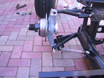

Last edited by Ralphy (1/09/2012 10:38 pm)
![]() Offline
Offline
The beauty of this layout - is it is trying to get favorable toe steer - and that will be useful.
Unfavorable Toe steer is what the C3 Corvette single trailing arm set up has - though small - and why I am moving off the "Jim's Giovanni" to a double wishbone, etc set up.
Cheers - Jim
![]() Offline
Offline
I'm confused! I was all out for anti squat and roll steer. Then I start to read in some performance suspension books that it's best to stay away from the sort. As far as performance, I think I understand that these things only add to complications. Squat and such can be remedied by springs, dampers and the sort.
Those forward lower links were originally designed by Arning to be much longer and go further under the driver. However they were to long to fit under a 90" wheel base AC Cobra. So he redesigned them shorter. So................ did he intend to have the roll steer they got? Longer would make less, no?
Ralphy
Last edited by Ralphy (1/09/2012 8:02 pm)
![]() Offline
Offline

I've been away for awhile but we began driving the big block MGB a couple months ago and I thought you'd like to hear how the suspension is working out. It's very well behaved. Wheel hop has never been an issue so far, although we have not wound it up and dropped the hammer because we don't want to break the T5 tranny. Still, it has enough power that a sudden power roll on can break the tires loose in second. I haven't noticed any squat or hop so far but maybe I'm just not paying close enough attention. Regardless it hooks up quite well.
JB
![]() Offline
Offline
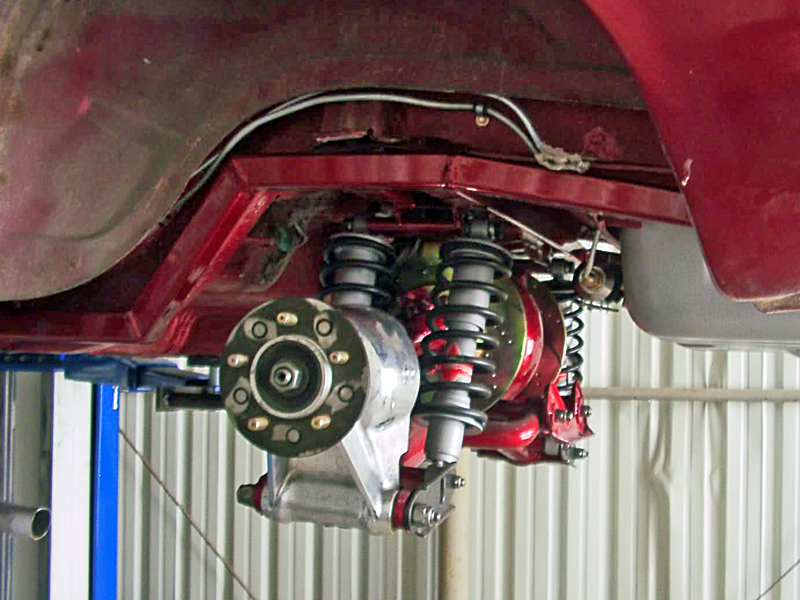
The lower forward link adds some roll steer.
I don't see anything from the picture that would indicate that.
![]() Offline
Offline
The link going forward as it travels moves in a different arc of the LCA. The arc is app 45 degrees to the LCA. In either direction the arc goes forward, this in turn pulls the LCA forward. This forward motion toes the wheel/tire in, ever so slightly. In turn you get a bit of understeer at the rear axle. As best I have found, the total typical toe steer is only app. 1/3 degree at max travel. Hope this helps.
The silver colored lower link in this picture is the link that induces the roll steer. Note, the suspension in this pic is not at ride height, it's hanging. Picture is looking to the rear of the chassis.
The lower forward link adds some roll steer.
I don't see anything from the picture that would indicate that.
Last edited by Ralphy (1/17/2012 9:40 am)
![]() Offline
Offline
The Live axle with the Watts linkage similar to a dirt track (bird cage) would do nasty things to the pinion angle. One of the big drawbacks to having a IRS instead of a Live axle is Traction under acceleration. For the most part it is easy to get a live axle to hook up with lots of built in anti-squat to plant the tires. Its near impossible to put equivalent anti-squat into an IRS with out wheel hop. With out any Anti-squat the IRS will never attain enough weight transfer to hook up l. I built new mounting brackets for the inner pivots on the LCA with out any built in anti-squat angle. The new pivot axis was parallel to the ground. The traction under acceleration was in a word abysmal!!! If I were trying to build a drift car, that's the set up I would use!! For driving in the real world some Anti-squat should be built in to these Jag suspensions to enable the rear tires to grab. The percentage of anti-squat is depends on the application and tire type... A Cobra with racing slicks will need far less built in anti-squat than my mustang with dot tires.
I plan on downloading lots of images after I have warm enough weather to paint my car. Right now it is all block sanded, masked off and ready for paint. The problem is its snowing and below freezing out. My ventilation system draws more air than I can possibly heat. I have a 4 foot squirrel cage duct-ed fan driven by a variable speed DC motor to draw paint fumes out of the shop.
![]() Offline
Offline
Ralphy
From what I have read, the 45 degree angle plays little role in roll steer. I always had the understanding that link was how the rear toe was set and it has no other function.
If you can find a copy, buy Engineered to win. This has to be one of the best suspension books I have ever found. The author has a whole series of Engineered to.... books for the construction of race cars and all of them are outstanding! The paper back copy (about the size as a phone book) I got cost me 80 bucks on E-bay but was worth every cent. Seriously, Its light years ahead of Chassis Engineering by Herb Adams
Last edited by tyrellracing (1/18/2012 7:08 pm)
![]() Offline
Offline
The Cobra 427 later called the 427 SC, Semi Competition sold for street use had the Klaus Arning design. The pic is from Club Cobra where some members are recreating the 427 SC.
This link will explain Arnings roll in the design. The article refers to the Cobra as having a similar or same design as the Mustang 1. If you go back in the article you will see. The Mustang 1 is what Duane Carling is building with roll steer. And by the way is a member here. The best way I can explain the pic is if that forward link were @ 90 degrees it would be called a trailing link. As most here know a trailing link will pull the wheel forward. At 45 degrees you still have a semi trailing link which still moves forward. Klaus Arning is the creator of roll steer, 1958.
March 1964.
Shelby-American enters a 427-engined Cobra, CSX 2166, at Sebring in the prototype class. Cobras, for the first time, beat Ferrari GTOs. Shelby meets with AC Cars and Ford design engineer Klaus Arning to develop a big-block Cobra.
The Klaus Arning article and these other two are from Duane Carlings site
Here's another way to look at it. The original concept for the Cobra by Arning was to make that link longer. But because of the driver being so low and near the IRS. The link would come up and hit the driver. Arning redesigned it shorter. So now imagine this link at a 60 degree angle going further forward. In your mind can you now see this link pulling the LCA forward? When I say 45 degrees I am approximating, I do not know the actual angle.
Just a little more AC Cobra history. Competition was catching up on Shelby. So the decision was made to go with the 427 Ford was building for NASCAR. At the same time the Daytona was in progress and being introduced. The Daytona was a much better areo design. Speed and fuel mileage was tremendous. So well on the Daytona was the speed they de-tuned the motor for better mileage. Why blow away the competition, just beat them. The AC Cobra was on it's way to being scraped. Efforts went to the Daytona the AC was out. Shelby had already built I forget maybe 25 cars to race. So they labeled them as the 427SC for the street and track. What does this mean? The 427 Cobra that so many are in love with hardly raced. The real winner was the 289. Then after, the Daytona which kicked Ferrari's azz. Shelby was then asked to work the GT40 by Ford. So after 2 years the Daytona was dropped. The GT40 was king! What a story in my eyes.
Engineered To Win, I will look that up. Phantomjock had listed what sounds like some good ones also. Can you post that at this thread we have started on books? My funds are on hold right now.
Thanks,
Ralphy
Last edited by Ralphy (1/18/2012 9:34 pm)
![]() Offline
Offline
For my link positioning. I copied the Klaus Arning design as closely as I could. The design was one of the first to have been proof tested on Fords new suspension computer program. This is the program that refined the GT40 as well as the 427 cobra's then new suspension.
I found a blue print on line of the Klaus Arning hub carrier but the dimensions were undecipherable. I had one Ace in the hole, I knew the bearing size and armed with that, I enlarged the image at work with their print copier, printed it at as close to full size as I could then scaled the rest of the dimensions with relative ease.
The hub carrier was the key to making this design work! From what I read the original design used the Vette stub axle and bearing. Kind of strange for a ford! I used the Jag stub axle and bearing dimension as well as the Jaguar carrier bearing separation. That way the hubs could be assembled the same proven way as the Jag with the parts I already had.
The front link attachment point was the front spring eye mount . I used 1/2 heims with aluminum spacers to fill the void and allow the bolt to pinch the ball firmly. The original carrier used a tie rod to connect the front link to the bottom of the carrier so it had a tapered hole. I changed this to two ears with 1/2 in. holes to support the heim in double shear at the same location.
The rear attachment used the threaded holes in the mustang frame rails that originally held brackets for tying down the vehicle during shipping. Klaus used these same holes for his rear pivot mounting brackets. The original rear links used tie rod ends on both ends. I made double ear type clevis mounts on the carrier and as pert of the frame mount in an effort to utilize 1/2 in. heims.
The LCA inner pivots were removed from the differential. I made new ones that had the same general foot print so the connecting plate could still be bolted on and used to jack up the car. The new brackets placed the pivot in the same axis as previous but I placed the clevis mount two inches forward of the center line of the disk brake. The opening for the 3/4 heim is 1/2 inch wider than the ball so I can shim the toe setting for alignment. I placed the inner pivot forward two inches to reduce the amount of goose neck in the lower arm required to clear the larger than stock vented disk.
I fell into a deal for another XJ6 rear for 50 bucks. (I mentioned it in a previous post) I took the LCA's to work and band sawed off the outer pivots at the weld then machined off all excess steel to make a simple "u" then welded two segments of 1.25x .125 wall round tube with off set bends to the "u" in a manor that from above looked like a 2 inch off set front control arm. Viewed from the front the goose neck at the inner mount as clearly visible. I took a 1.25x3 round solid bar stock. Tap drilled for 3/4 unf threads and tapped it the same then welded it to the union of the two tubes. The coil over mounts were then moved outward 1 inch and lowered to the bottom of the tubes because my AFCO shocks are a little longer than the stock units and this helped to compensate.
Well that sums up how I altered my IRS to eliminate wheel hop. I didnt take any pictures when I built the parts but I will as soon as I have paint on the car and can tear off all the masking paper.
PS You are absolutely right The 289 Cobra won the majority of the races . Ironic how every one loved the 427. The men who raced the 427 cobra said it was a tank to drive compared to the nimble 289. The 427 took much more effort to man handle it around a course and was totally unforgiving to driver error. The nose heavy 427 could be off set by its over abundance of torque that was used to throttle steer and rotate the car around the tight turns. In the right hands they were ballistic on most road corses, The unskilled were often made dead from the learning curve. This one car is what started the manufacturers to give fake low hp ratings for insurance purposes. It got tough to sell cars that could kill an average driver with in a month of buying it when you cannot insure it.
![]() Offline
Offline
The guys doing the replication of the 427 SC at Club Cobra. They have the blueprints of the entire chassis, you can buy them. Thinking they cost about $600.00.
I forgot one other big fact, the majority of the 427 SC's came with 428 motors not 427's.
Here's another way to look at it. This is an overhead view, do you see a bind? And which way is the bind. Same as the 427SC but an added inner pivot point to the LCA. My mind says the LCA will be pulled forward, but honestly I do not know. One thing I think, the points have to be spot on to get what you need or want. You would have to use a computer to crash numbers all over it seems. LOL!
And isn't the Arning design the same or similar to this?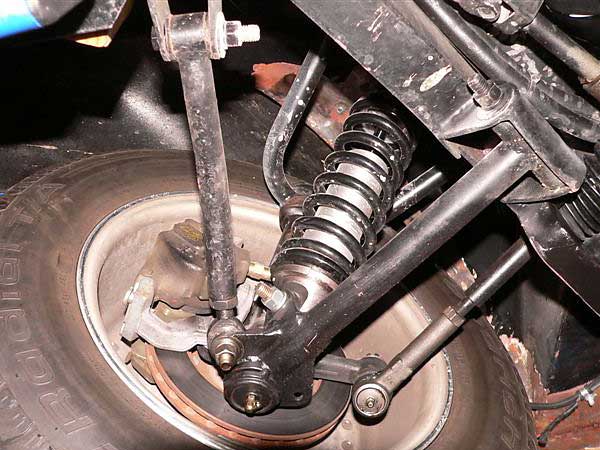
"I found a blue print on line of the Klaus Arning hub carrier but the dimensions were undecipherable." Let me guess it probably also said, DO NOT SCALE. LOL!
Last edited by Ralphy (1/19/2012 9:06 am)
![]() Offline
Offline
OK, I think I see the key! I do best when I look at something in an extreme form. The key is the distance between the inner pivot of the LCA and the forward link inner pivot. That is, the variation of the two. Notice the LCA is further to center on the 427SC. The shorter the length of the forward link, widening the gap from it to the inner LCA pivot. The more forward motion created, the greater the roll steer. If both were at the same point, it would be neutral, no fore or aft motion. Then if the forward link were inside the LCA, the LCA would move backward. Sorry I included the inner center pivot on the LCA, it should be removed.
In this chassis walk around, you will see the LCA is approximately 2" inside the forward link. Typical Cobra 427SC main tubes were 4" dia. I believe. The 15 second mark gives a great rear view.
Last edited by Ralphy (1/19/2012 4:57 pm)
![]() Offline
Offline
TR,
Is this the book?
![]() Offline
Offline
Thats a good one too!
If - as you do machine work - you want one for the "shop"a great one he wrote is; Carrol Smith's NUTS,BOLTS, FASTENERS, and PLUMBING.
Focuses only on the components and bits.
CHeers - Jim
![]() Offline
Offline
YES that's it! I have read my copy so many times I can find important topics by where the book opens to by its self when placed on its spine.
The free body diagram you drew is not what is in the picture. Also since the LCA uses heims and connects to the frame at two points you can draw a tangent line through the center of the ball on each of the inner heims and you have the pivot axis. Their is no third connection point from the LCA to the frame the way you drew it. The fact that the pivot axis are is not parallel to the center line of the vehicle may appear odd but is more common than some people might think. The one in your image will produce either reduced squat or enhanced squat. I haven't made a free body diagram and really looked at the kinematics yet.
This type of rear suspension is very common if you have studied the F 1 race cars of the late 50's and early 60's. I have a old book written by the chief engineers of the LOTUS racing team from the same period. They explain exactly what the designs were like to develop and improve . The two of them went on to design several winning Indy cars, They designed cars for Carl Shelby, Dan Gurney and AJ foyt to name a few. They were at the front of the pack when Airfoils were introduced to F1, They used torsion bars not only for anti sway but front to rear for anti squat on some Lotus cars and showed how the did it. !If you can find a copy its called RACE CAR DESIGN AND DEVELOPMENT by terry and baker This book has the exact same rear suspension in it when they developed it for the 59-61 seasons. The book is full of technical drawings and how they designed these cars, the pit falls and best of all the solutions to all the different ailments that starting from a clean sheet type designs can bring about. These two guys did not have computers to crunch their numbers. These guys knew their stuff and if you can find a copy you will find it to be a wealth of suspension knowledge. Damn good reading!
Your free body diagrams would produce a suspension that could not move. That style design usually as an upper arm with two points on the frame and one on the upright. Then a lower with two points on the upright and one on the frame. The lower has an additional link for setting toe but the lower never has three mounting points from the LCA to the frame. The way you have drawn your free body diagram either the LCA or the frame would break before any wheel travel could happen. From what I see, It just cannot work that way. Klaus used a simple wish bone with two points at the hub and one at the diff. Toe was set by moving the one point at the diff to the front for more toe out or to the rear for more toe in. Far simpler than your drawing.
![]() Offline
Offline
JIM...
BTW yes I have a copy of that one too!
![]() Offline
Offline
TR said, "Their is no third connection point from the LCA to the frame the way you drew it."
That's what I said in the post. I'm going to redo it. That point would cause a bind as I mentioned in the earlier post before that one.
"Sorry I included the inner center pivot on the LCA, it should be removed."
I don't know how you can determine what the squat would be from a two dimensional overhead sketch view. Since there is no vertical planes seen. Anyhow if I see the 427SC pic right the forward link mounts low in back and high in front. I would guess maybe that would give some anti squat.
Here I erased it. 
Last edited by Ralphy (1/19/2012 7:20 pm)
![]() Offline
Offline
TR,
Do you really want anti squat? Or do you really want those tires to just drive into the asphalt as hard as possible and stay? What I'm saying is the further back the trailing links mount to the chassis the less weight they have to raise. Giving a higher chance of jacking the rear up under hard throttle. A C4 Corvette is an example of this. Your setup has your lower link much further forward. I can see several advantages with this. This for one creates less jacking. And also when cornering on and off throttle would cause less, would it be roll or yaw? I can see a C4 Vette maybe getting a little twitch breaking traction in a turn. phantomjock may know. For street and drag racing this may be good. But for performance cornering seems not. That's where I think the double wisbone excels, moving the fore and aft forces more to the center of the chassis even with anti squat.
Some squat is good. And as my drag race buddy said, "the weight can only be in one place when the front wheels are off the ground."
If I went your route, I have room for a 21" long lower trailing link. The Cobra guys running the C4 IRS, are using trailing links about 8" long. You can see it here. The back end of the link is in front of the H/S as you probably know. They keep the same geometry on the links as factory. The four inch square tube in front of the tire, on the frame. Is where I would go with the T5 design, if I go that way.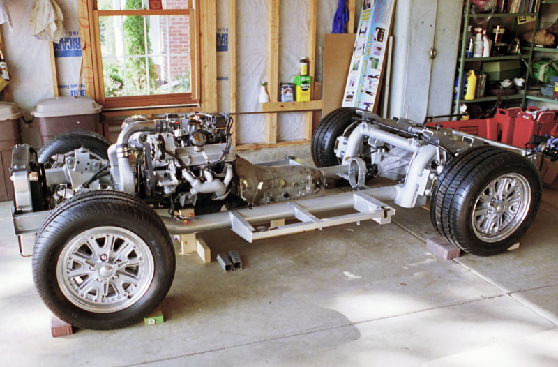
Last edited by Ralphy (1/19/2012 11:03 pm)
![]() Offline
Offline
That makes sense now. I get how this can induce roll steer but my question is.... Why would you want to induce roll steer in to a performance cars suspension? Most people with vehicles that have roll over steer hate it. And roll under steer was designed into stock vehicles to make them predictably poor handling . This was to keep novice drivers in control of their vehicles, not to improve the ability to generate lateral G's You have one of the most versatile platforms from witch to build. The large diameter tubes in the ladder frame have outstanding torsional rigidity and a relativity good strength to weight ratio. IMO the Cobra is a stunning body to wrap around it.
Am I missing something ? Is there a benefit to creating roll steer into a car that with out it ,you could make it corner like the roads were made of fly paper?
The more I look at the differential housing in the cobra frame, The more I am sure that must have been a failed idea they didn't think all the way through. On dirt track cars they employ a linkage called a bird cage that look identical to what was pictured with one huge exception. Bird cages have bearings and allow the housing to rotate freely inside them. The reason for a bird cage is to control fore and aft movement of the housing.The rotation is controlled by a type of torque arm.
![]() Offline
Offline
WOW! Let's back up.
First you mentioned in a previous post the 427SC was un-drivable. That was because it originally had the 289 suspension like this below.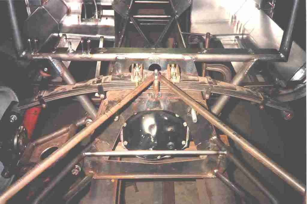
That was the inferior suspension that caused the uncontrollable 427. So Arning steps in with his new at the time roll steer design below.
This was 1965 never seen or used. Since that time racers have found roll steer a bit quirky. So for racing, it was scraped for a more conventional design. The kit car guys are building this design, trying to create as close to an exact replica 427SC.
Then you just now you said people who have roll steer must hate it. But you have it, with your T5 copy! Not sure where your going., that's roll under steer not over steer. All Arning's designs created under steer. For racing you never want over steer. That's one of my C3's flaws. Maybe drifters want it or dirt racers. Not on asphalt.
Last edited by Ralphy (1/25/2012 8:38 pm)
![]() Offline
Offline
As far as the T5 design, I have plenty of room. This is the same frame I have, No clearance issues at all.
Here's another car with the same frame as mine. You can see why an IRS is so desirable in a Cobra. My drive shaft is only 10" long.
That 427SC Arning, Really gotta wonder how well it would handle pot holes,
What I also like about your design the T5, is that you can dial the amount of roll steer to your liking. You can even remove it completely.
Last edited by Ralphy (1/20/2012 7:42 pm)
![]() Offline
Offline
I have no problem with wheel hop what so ever now. The description you gave applies more to a live axle with under ride traction bars. My linkage applies near equal force to both leading and trailing arms and as such does not produce as much lifting force to the body. The forward force is divided into the two links. The portion of thrust pushing the car forward through a angled leading link , when broken into force vectors will give some lift. No where near what the Live axle did with under ride traction bars. When axle rotation was applied to a lever arm, it would physically lift the car under hard acceleration. I had the old Nine in. dialed in very well for the standing start. If a line were drawn through the link it would start 6 inches below the axle housing and go through the centroid of vehicle mass so when the car launched the link would literally lift the whole car and plant all that weight on the rear tires. This is very near 100% anti squat. This amount of A.S. cannot be achieved on an IRS. The only examples I have seen gain that good of traction with a IRS did it through an ultra stiff springs and racing slicks. not A.S.
The K.A. set up has yet to show any down side other than it cannot initiate the grip required to produce weight transfer under full throttle acceleration. Non judicious throttle application will get you sideways quick. The main reason I switched to the IRS was for lateral G's. The roads around here are often nothing more than a series of filled pot holes with a little asphalt in between. The un-sprung weight of the nine in. rear got real spooky when pushing it around corners on Oregon's typical rural roads. Snap over steer was my most dreaded problem.
 1
1 