
 |
 |
 |
 |
 |
You are not logged in. Would you like to login?
 1 of 1
![]() Offline
Offline
Decided that this needs it's own thread as I intend to fully dovument the "How to do" of this conversion.
Gave up on doing what some one else had done and actually made some progress today.
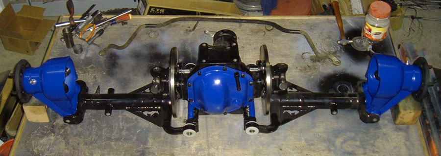
Mostly cutting metal but I think I've figured out how to mount the Sierra/Merkur diff!
Good thing since it was keeping me awake.
Pics once I'm a little further along.
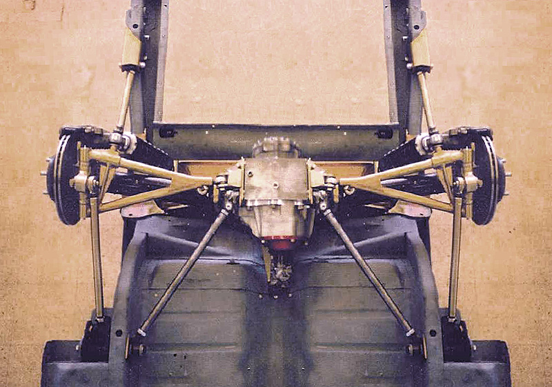
Basically I cut away most of the original Sierra/xr4ti diff cradle except for the mounting plates and a small section of the curved tube between them.
I plan to weld some rectangular box section steel vertically to the ends terminating at horizontal brackets that will fit the original Triumph mounts.
This is similar to how Toyota and such are usually done.
In addition I also cut away the center of the rear body mount for additional space.
I will now be able to add a horizontal bar to reinforce it while also fitting an original rear Siera/Merkur diff mount.
Hoping I can get one in Poly as the original rubber is too soft for my preference.
Once done the diff will be able to drop out the bottom easily as original.
I am off-setting it a bit in order to have equal length axle shafts.
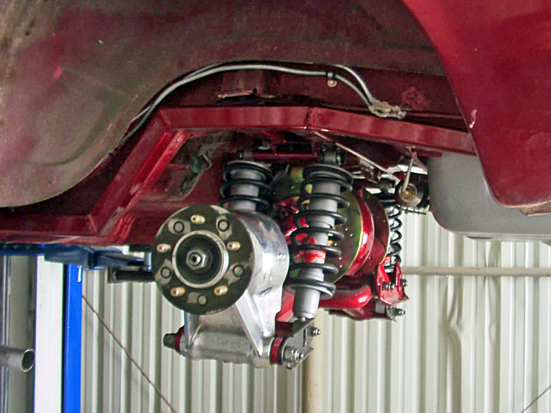
With the diff in I will be able to work on the A arms, uprights, and shock mounts.
Since this is not a sanctioned racer there are no set rules and I am free to do whatever I like for suspension.
Anyone have an "Ideal" rear suspension geometry for a 49" track and 185/14 tires on 6" rims with 4" back space?
![]() Offline
Offline
Had not planned to do so but put a few hours into fitting the engine and trans today.
Finally have them sitting just about as perfectly as possible.
Cannot get any lower even if I had a dry sump system, bottom of the pan is even with the bottom of the frame.
Engine is dead level with the frame, I may want to raise the front just a fraction.
Front of the crank damper is just about flush with the forward edge of the front cross-member.
If I cannot get the bonnet to fit without cutting now, it cannot be done using a Buick V6 engine..
Aghast at how much of the frame channel I've had to remove for that big fat T5 and the V6 starter.
Going to have to get very creative to restore the frame strength.
Looking like I will take a page from the old Shelby Mustang, putting a removable brace between the shock towers.Find this advisable since I've had to remove some of the original gusseting to clear the oil pump.
Also cutting clearance for the front pulley in the forward cross member.
Reversing an aluminum single sheave SBC crank pulley will give me enough room to move the steering rack back 1.00" which seems to be all that should be needed.
Doing that and shortening the rack to fix the backward Ackerman and bump steer.
No room to mount the alternator in a conventional manner so current thinking is to reverse mount it.
The water pump drive may become even more bizarre, perhaps utilizing a jack-shaft from the alternator if I cannot make an electric pump fit.
Just about ready to actually put the front engine mounts in.
Would be nice to weld parts ON after so much cutting them off.
Still not certain about the front suspension.
I recall reading that some folk have adapted European Ford spindles and arms.
Since I need a 4x10⁸ pcd anyway I will look into that as well.
Once the engine and trans are finalized I can also finalize the mounting of my rear diff.
From there rar suspension mocking up should be much more accurate.
Last edited by Richard/SIA (9/13/2015 9:04 pm)
![]() Offline
Offline
Not directly related to the IRS but necessary in order to be able to check driveshaft length and angle.
Finalizing fitment of the engine and trans which requires heavy frame cutting.
Not actually building a frame but with the number of modifications it almost feels like it.
In order to get a Buick V6 and T5 to sit low and back in a Triumph GT6 frame I had to cut away most of the top and half the inside vertical wall of the forward half of the "Hourglass" portion.
Pics once I clean things up a bit.
Really want the bonnet to remain stock and do not want to put thick spacers under the body, it's sports car not a 4x4.
I will also be putting a curve into the top of the front cross-member to clear the crank pulley.
Crankshaft damper sits flush with the front edge of the cross member, that may give an idea how far back I'm setting the engine.
Think I figured out how to reinforce the frame.
Going to have some rectangular section steel bent to match the chassis shape where it's been cut away.
This will need to be as close to the inside width as possible and half the depth.
That will be welded inside the original chassis, which is even thinner than I had expected despite having no rust.
This restores the frame to a shallower box section.
Then I want to add another bent box section to the inside outside edge, about a third of the original width but flush to the top of the original rails.
That gives me a doubled up box section that I think will probably be stronger than the original when welded full length.
But it still leaves the extra inside width and depth I need.
Now to find a fabricator who can do the bends.
Hope my description makes sense, I have no idea how to attach a drawing even if I had one.
Also looking into changing the front IRS to eliminate the weak lower trunion.
Anyone know if 71-73 Pinto upright is actually the same as late Cortina?
I have confirmed that they are NOT the same as 74-80.
Slightly smaller and lighter, with a 4.5" arm instead of 5.0" as the later type use.
Vendors who list "71-80 Pinto/Mustang II" as all being the same are incompetent at best.
![]() Offline
Offline
Looking forward to your updates..
As far as your question on the front lower trunion, I am building my own LCAs and using thread in ball joints and the Chevy nova spindles.
I picked up a Thunderbird 8.8IRS, going to finish up tub before I start fab on the IRS. Still undecided if I an leaving tub stock or flared wheel wells..
Please post some pics of yours, sounds like you are way ahead of me on the fabrication side....
![]() Offline
Offline
Mocking up the rear now that I finally have some aluminum uprights.
GT6 frame creates an issue I need to find a way around.
Original suspension used a lower arm and the top mount transverse leaf spring.
I'm using an upper and lower arm.
The main obstacle I keep running into is that the lower arm will have to be fairly short at about 8.50".
Normally the upper arm would be made a bit shorter.
That makes the upper arm VERY short in my view, particularly with the offset incorporated in the upright, so only about 4.00" for the arm.
So now wondering, can I get the camber compensation I want using upper arms that pivot from a point past frame center?
Left arm pivot point to the Right of frame center, Right on the Left.
This would be similar to what Triumph did, the leaf spring brought the pivot point to near center.
Every model suspension I look at features long A arms, nice for a scratch built frame but I do not want to have to cut away my original rear frame.
I do have a suspension modeling program but not a lot of expertise with it.
Not sure it will accept this idea to analyze.
![]() Offline
Offline
Got better numbers and tried them in Speed-Wiz.
As I suspected it will not let me go past center for my calculations.
I can get very good numbers and avoid positive camber entirely for bump and lift, but no matter what I try I cannot seem to avoid negative camber on the out-side wheel in body roll.
Probably missing something basic, but what?
So far I've mostly kept the lower arm level and played around with upper arm length, and some variation in inner pivot point heights.
Looked at my frame and the numbers I was happiest with.
Looks like a simple set of cross-mounts and reinforcement will work.
May also be able to attach the upper diff mounts to them.
![]() Offline
Offline
Closing in om my design.
Looks like I will be shortening the aluminum uprights I bought.
From 10" bolt to bolt vertically to 8.5".
This will also reduce the kick at the top around .75", need to fixture them for better measurements.
Still wrestling with weather or not to use equal length upper and lower arms?
Upper mount can be whatever I need, lower is pretty well dictated by the frame width, about 9" long max.
I have some pretty good numbers using equal length arms but am not getting the type of camber change I want.
Looks like the lower shock mount will have to be to the top of the outer end of the rear arm link.
Not ideal but lets me retain the original upper mount.
Speaking of the arms, my plan is bushes at the inside and rose joints for adjustment on the outer ends.
Would actually prefer bushes at both ends but the adjustable type I would need do not appear to be available in a correct size and would be a real chore to make myself.
![]() Offline
Offline
Looks like 1.00" x .120 wall for my control arms.
Kind of would have liked a little thinner but I have this on hand already and it is mostly a street car.
Trying to work out the mounting tabs, a real joy as NONE of the frame members are strait, parallel, or level on a GT-6!
Makes reference points and measurement a wee bit difficult.
Using some rectangular box steel for simplicity in keeping the tabs parallel and properly spaced.
Looks like I will also use the old tabs to create my datum line.
Had considered mounting the arms a little lower than original but that might put them in reach of speed bumps at the frame end.
![]() Offline
Offline
Think I found some useful reference points to measure from.
That lets me mark the chassis so that I may get the mounting tabs evenly placed on each side.
Driving myself crazy trying to configure the upper mount points and arm length.
The lower is pretty well fixed at 8.5" by the wheelbase, uprights and ride height.
So my camber gain has to be done from the top.
I must be doing something wrong as all the examples and advice I find insist that the upper arms should be shorter than the bottom.
But I seem to get better numbers with a significantly longer top arm.
Equal length gives good result in bump but goes bad on body roll.
Unequal not as good on bump but better on body roll.
Seems no matter what I try I still get +camber to the outside on body roll.
I thought it was supposed to be possible to get -camber on body roll?
 1 of 1