
|
|
|
 |
 |
 |
You are not logged in. Would you like to login?

![]() Offline
Offline

What if someone could design a suspension that gave more anti-squat the more the car squated? What if someone could build a suspension that combated body roll the more the car rolled? Would you want this design? Maybe?
Ralphy
![]() Offline
Offline
No ones taken my bait yet! ![]()
I think it's been built. I think most here have looked at it or seen it. ![]()
Ralphy
Last edited by Ralphy (9/30/2012 5:04 pm)
![]() Offline
Offline
Ralphy -
there have been a number of neat approaches.
The Watts Linkage and it's variations - and the venerable
Milliken 1960 MX-1 Camber Car:
and a nice rear view:
Or, the hydraulically operated Body Roll Tilt mechanisms ~ perhaps?
Sorry been welding wishbones and doing attic chores all weekend - couldn't play along!
But, thought these would be fun!
Cheers - Jim
![]() Offline
Offline
Damn! ![]()
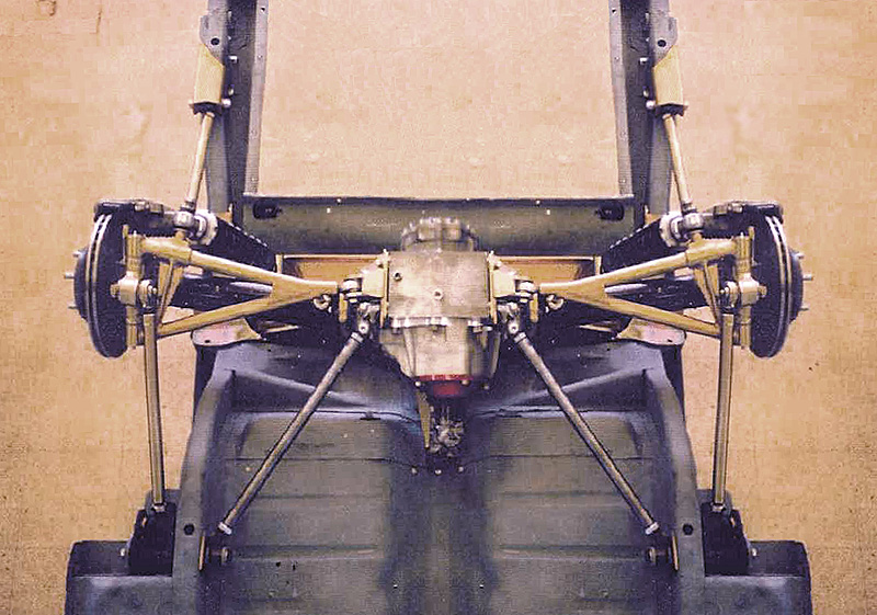
Phantomjock is the winner. I'm a little stupid and slow. However I spent some time the other day trying to dissect the KA T5 design. Seems I spent too much time thinking the lower trailing link was the primary link/area. The upper rear is where the real action is. Looking at this link closer I noticed it's much closer to the half shaft meaning a higher amount of acceleration/braking forces go through it. Second, being further to the rear means it takes less effort to affect the chassis height/jacking. Then third scaling the home page pic. I can guess it's only 75% of the length of the lower forward link which means it can gain more angle per inch of travel. The upper rear link on the KA T5 Watts design is the primary link. As the car squats the rear upper link comes more into play with higher angular forces than the lower can ever create. Looking at the opposite, rebound. The link rotates to reduce any jacking the lower forward link creates. Being useful in cornering.
This is all theory I know because I never drove a car with a Watts. I still can't figure out how it affects braking and that's what always had me baffled and still does. Gold star for PJ saying Watts! LOL!
This view you can see the length difference between the two trailing links.
Here you can see how much closer the rear link is to the HS center line.
PJ what more have you read on Watts designs? Does this still have a negative effect on corner handling?
And why are the HS's rearward? Increases the camber curve? Is it just a placement issue being a convenient location for the differential?
The Milliken 1960 MX-1 Camber Car led me to, Mercedes-Benz F400 Carving Concept Info. However off the topic.
Ralphy
Last edited by Ralphy (10/01/2012 6:34 am)
![]() Offline
Offline
Ralphy _
What DID I WIN???
Here are a few shots of another - REALLY COOL Set u p - The Dax system uses rods from one side of the suspension which link to the wishbone pivots on the other side and move the location point of the wishbone.
In this way it provides some camber compensation. And importantly, the tire is held at the best angle to the road. This maximizes grip for that the tire. This may be off camber to the road to but could allow for the tire deformation and keep the tread flat to the road -- REMEMBER we start with the Tire! . Now, it could be easier to keep the tire contact patch at the optimum wiith thee Dax system over a wider range of movement.
set up - the DAX suspension:
and:
Attributed appropriately to :
A few concerns - (I've not verified)
here are some inherent issues that DAX may not have addressed (TBD):
1) One wheel bump
2) Steering geometry (front wheel - or all wheel steering)
3) Radial tires require some camber to help traction (camber thrust) AND all seem to be happier at 10 degrees slip angle or so
4) Stability from side to side (picture grabbing the top of one tire and rocking left to right) Severe body roll(?)
Just a few interesting items to distract -- while we should be Building!
Cheers - Jim
![]() Offline
Offline
Something else I see with the T5. The coilover being at the rear. If you understand the upright rotating clockwise when rebounding. Because of the lower trailing rod rotating forward and the upper rearward rod back. This unloads the the inside tires spring at a faster rate when cornering. This causes the coilovers lower mount to fall away as it rebounds/releases. Not only that but this loads the outer coilover faster initially. So you should see less body roll in cornering. If the coilover were to the front of the HS, the opposite would happen. Which would be a negative effect.
I'm trying to figure out the motion of a toe rod behind the HS like the Giovanni C3 design instead of two lower mounting points as the KA T5 camber toe arm. Equal length to the HS and parallel. As best I can see without plotting. Is that the inner tire will toe outward. The outer will stay put. The inner rotates due to the fact the toe rod will drop below the HS again, because the upright will rotate clockwise. The amount should be slight. I need to calculate real numbers. This may minimally promote roll steer.
You win a free trip to Fla. LOL! I've seen that design before, it makes me ill trying to follow the links visually. But for some strange reason I understand what it does. There's a working model, if you click how it works at the link.
Ralphy
Last edited by Ralphy (10/01/2012 10:59 pm)
![]() Offline
Offline
I came up with an approximate number for the unloaded wheel toe. The toe link being 7" behind the HS would drop .346 below the HS. This would toe the unloaded wheel out .523 degrees at 2" of travel. The upright when unloading would rotate app. 2.837 degrees. The vertical distance I used at the upright between the upper and lower link was 8". You could also lengthen the toe link like the C4 which would give an effect more like the C4. I'm really not looking for roll steer. Playing with the inner location of the toe link may result in improvements.
I crunched these numbers with a forward link 22" forward with a 2" drop. The rear link being level and 16.5" at 75% length to the front lower link. Also the 2.837 degree rotation of the upright creates an affected drop of the lower shock mount .197" at rebound. If you ran 400lbs. springs it would equate to a 79 lbs. loss at 2" of travel.
Ralphy
Last edited by Ralphy (10/02/2012 9:34 am)
![]() Offline
Offline
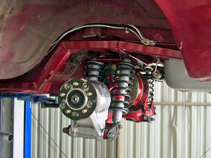
I have enjoyed the way my modified T5 suspension has enhanced the way my mustang corners ever since I installed it. It is so stable and roll resistant I had no need for the rear anti sway bar I used on the Jag design. I also abandoned the stock Shelby front suspension and went with a copy of the Griggs GR350 front suspension. It too made a dramatic improvement over the antiquated mustang design. Griggs claims to have achieved 2 G cornering forces with street tires when his complete suspension systems are installed in both late and early mustangs. I have yet to record these same results partly due to the fact I am using much smaller section width tires however I have gained .4 G on the 300 ft skid pad over the enhanced mustang front with hotchkiss drive live axle rear suspension.. The same 245-45-zr 16 tires and wheels were used for all of my skid pad testing.
By the way. P.J. Neat find on the Dax suspension. It looks like a true original concept and not just another modified example of different spring linkages on the same old stuff. Very interesting concept. . One concern I see is there would be a change in toe with the movement of the upper control arm. That would generate bump steer.
Last edited by tyrellracing (10/04/2012 6:22 pm)
![]() Offline
Offline
The DAX has been very successful in the UK on the LOCOST (Lotus Super 7 replicas mostly) circuits. Flat cornering etc. Think their website (might expect that) has some of the race details.
Here's a link to some scanned pages from Racecar Engineering on the DAX - camber compensation System:
tyrellracing - nice improvement - near 1/2 g!
Cheers - Jim
Last edited by phantomjock (10/05/2012 2:43 am)
![]() Offline
Offline
Back to the Watts link. Now that I better understand how it directs force. I'm also noticing the Jag with a LCA and a upper Watts creates a very neutral effect. Since the forward link cancels the back link and the reverse.
Ralphy
Last edited by Ralphy (10/05/2012 7:30 am)
![]() Offline
Offline
Too bad when he was moving the upright (in the video) he didn't show the camber change. - Thats a reminder to myself - when I getthat far along - I guess.
Cheers - and nice post Ralphy.
Jim
![]() Offline
Offline
When I changed my Jag IRS to the modified t5 I extended the upper or rear link mount on the upright so the link connection was the same distance from the axle CL as the lower link connection . Then I lowered the rear frame mount so there was a tangent line from the front frame mount to axle CL to rear frame mount at normal ride height. This created a true watts linkage that with the suspension travel produces no fore and aft movement. This also equalizes the loading of the front and rear links.
This is why I stated the KA T5 toe change graph did not apply to my set up.
When I built my uprights and frame mounts I put 5 mounting holes on one inch centers on each so I can go back to the exact same geometry as the T5 or a variety of other combinations. That is why I described my design as being tune able. This is how I generated the numbers Ralphy claimed I guessed months ago. My current set up does not generate a change in toe nor roll steer of any amount worth mention with travel.
The whole reason the stock T5 produces a change in toe at all is because the axle is not centered between the forward and aft linkage mounts on the upright. Since in stock form the T5 axle is not centered the front and rear links cannot cancel each others motions out
The forward and rear links on the T5 are not different lengths. The image might make them appear that way but in reality the only difference in length is made up by the adjustment of the heims. In stock form the rear link of the T5 carries the majority of the loading in the fore and aft directions. The rear link also has the weaker mounting point
When I was satisfied with the Griggs suspension I built and set up on a spare mustang nose, I changed my Shelby over to the Griggs GR350 front suspension. This required that I change the single T5 lower control arm per side to a twin LCA per side on the T5, When combined with new inner LCA mounts allowed me to move my roll center to a location that would complement the Griggs front suspension. It also made toe change much easier. I still use 4 coil over shocks on the rear suspension with one on each LCA. The rear units have 260 lb/in and the fronts have 140 lb/in spring rates.
Getting rid of the roll under steer Klaus Arning put into the T5 rear suspension was required to have predictable high speed cornering. Roll under steer generates some serious undesirable traits in the transient portion of corner entry. The roll steer effects of the T5 may seem to seem useful on paper but they can be deadly in a wide sweeping 120 mph corner entry
![]() Offline
Offline
Good catch on the rear link length. The side photo gives an appearance they are equal length. However the underside pic gives the appearance the rear is shorter and I scaled the pic. What I did not take into account is the depth difference of the two in the picture. Since the rear is further from the lens it will appear to be shorter. It's a distance thing! They must be at least close to equal as far as pictures go. Giving almost no variation/rotation.
If you have a lower trailing link 22" between mounting points horizontal. If the vertical drop between the points is 2" anti-squat. The link will be 22.090" long, so now if you compress/jounce 2". The distance will now be 22.090 horizontal, pushing the wheel back .090". If the LCA is app. 18 " long and rotates/moves the uppright back .090". You toe the wheel out app. .286 degrees. So the LCA would have to be adjusted accordingly to give zero roll steer. At least that's what I trig-ed.
As far as the the RS is achieved I am still not in agreement. The front pivot between the LCA and the upright are at a higher point than the rear pivot. The moment at this front point is almost dead nuts horizontal, again at the front. Any jounce will now start a rotation that will go inward. It's achieved it's furthest point out. The rear upright pivot point is below center. When it starts it's upward motion it still has some outward motion left. So the front starts in, the rear starts out, rotating the upright inward at the front and outward at the rear. The further the LCA travels from horizontal the greater the difference the greater the toe in. If in doubt imagine rotating the LCA straight up 12:00 the front will arrive app 1" sooner than the rear. As explained in the KA articles the more you rotate the LCA, the greater the RS. You increase the timing difference between the front and rear pivot points.
This is why I once brought up twisting a conventional two point LCA such as the T Bird. If you were to twist the front upright point above the rear you would be adding RS/toe-n in a jounce condition. You advance the timing of the front point. If you twisted/raised the front point 1/2". Freely took just the LCA and upright while keeping the upright, upright. You will see the LCA at 12:00 the upright will be turned in 1/2".
That's my story and I'm sticking to it. And that's the end of my discussion on this.
Ralphy
Last edited by Ralphy (10/06/2012 7:02 pm)
![]() Offline
Offline
I did not mention that with the relocation of the lower control arm came a change in ride height. That was the only way I could keep the control arm level with the new ride height. The lower control arm plays no role in determining the roll center. Ride height does.
Your assessment of the change in toe is flawed because with out measuring my actual set up you cannot locate the rear link frame mount nor can you determine where the upper mount on the upright is located nor do you know my ride height. Not knowing any one of these points would throw off your math. Not knowing all of them makes your efforts pointless. Your math based on guessing has little meaning. Nice try but but with out putting a tape on my car you can only guess. Every number you based your math on is wrong. Keep in mind my half shafts are Jag and therefore longer than the T5 image you scaled. Not only that the T5 image you have is from a 65 mustang. Mine is a 67 and is larger in nearly all dimensions Posting your guesses as some type of proof is at the very least is rude.
When I set up my Hunter laser alignment heads on my rear hubs and aim the laser on a target at the front of my car the laser dot is aprox. 3/32 in dia. With 4 inches of travel, 2 up and 2 down the laser dot does not move more than 1/16 inch. This measurement was taken more than 20 feet from the light source. In all reality that is an insignificant amount of change. That is far less than your .286 degree
Have you even built your IRS or are you still talking about it?
![]() Offline
Offline
I don't think I mentioned Roll Centers once, that would be RC. I typed RS and roll steer, both.
So let me ask you this. You once said your front trailing link sits app. at 25 degress static. Is your rear link parallel to the front link, static? Both app. 25 degrees to level of the ground, lower at the rear of both links?
Ralphy
Last edited by Ralphy (10/07/2012 9:34 am)
![]() Offline
Offline
When did I declare any angularity dimension of the front link? If I did ,and I doubt it, The ride height has been changed enough times since then to make such information obsolete. I have even built another set of uprights that do not have tapered roller bearings for the LCA. With 3/4 Heims on the LCA's the bearings in the upright becomes redundant.
The first set are going into my Sunbeam Tiger. The Tiger will be my second IRS conversion. I just finished the replacement of the Tiger's K member and built a front suspension that is virtually identical to the Griggs racing design I built for my mustang. I already had the welding fixtures.
The line from the front mount through the axle CL to the rear frame mount is within 2 degrees of the road surface depending on the front to rear ride heights.
I own an inclinometer and use it often at work to double check my sine table setting. It is guaranteed accurate to .0001 per foot. That's the manufacturers description not mine. but I don't recall having ever measuring something as pointless as the angle of my front link.
![]() Offline
Offline
I'm trying to get a visual of your setup since you don't post any pics. So now the lower front is at 2 degrees and the rear is at 10 degrees? That's a first, saying trailing link angles are pointless, OK. If that's so, why do you keep changing the angle?
From your post 1/22/12.
"As to your $64000 question. I have the car on a center lift with the wheels at full droop. This gets them out of the way for painting. My best guess on the leading link would be between ( 25 and 30 degrees) from the bottom of the hub carrier up to the frame at normal ride height. The trailing link goes down from the top of the hub carrier to the frame aprox. 10 degrees"
My calcs at 22" length @ 2" drop I would have a 5.2 degree drop on the lower link.
Ralphy
Last edited by Ralphy (10/07/2012 10:05 pm)
![]() Offline
Offline
TR you said,
"When I changed my Jag IRS to the modified t5 I extended the upper or rear link mount on the upright so the link connection was the same distance from the axle CL as the lower link connection . Then I lowered the rear frame mount so there was a tangent line from the front frame mount to axle CL to rear frame mount at normal ride height. This created a true watts linkage that with the suspension travel produces no fore and aft movement. This also equalizes the loading of the front and rear links."
Huh!
Your front trailing link goes downward to the upright as you stated 2 degrees. Your rear at best guess as you stated months ago goes upward at 10 degrees to the upright. Above you say you have no fore or aft motion at the wheel. Your front lower link travels a short bit to zero degrees and then starts back in the direction it started in under jounce. IT REVERSES! Then the rear is at app. 10 degrees and keeps increasing it's angle, moving rearward more rapidly than the front lower. But again your saying your wheel centerline never changes? LOL!
A motionless Watts has to have both links in the same direction at the same angle. Then you won't have any fore or aft motion. Just like in this video I had posted earlier.
As best I can tell what your describing, your wheel center moves rearward 6 degrees at jounce.
Ralphy
Last edited by Ralphy (10/09/2012 3:50 pm)
![]() Offline
Offline
Now let's analyze this statement you made.
This required that I change the single T5 lower control arm per side to a twin LCA per side on the T5
Holymoly Dick Guldstrand!
I've described why your upright does move fore and aft but if your mind and mine can visualize the fact it's also rotating. Any double lower links will cause toe effects. Dick Guldstrand understood this when he built his C3 concept.
In order to guarantee no rotation he used equal length parallel trailing only going forward. There is no way possible you can remove rotation with one link going forward and one backward. If rotation was to come into play, say the front camber/toe link moving above the rear camber/toe link. It would change the cord length. I don't care how you have two camber/toe links oriented.
Now let's go to the original mail you sent to me on 1/19/2012
"Look at the first image in the FORD IRS forum.. That is a underneath view of Klaus Arnings rear mustang suspension. I have the same setup in my car with the exception that my design uses two afco coil over shocks per side and a Salisbury center rather than a ford 9in."
TR, your all over the place. At another time you posted you use the single inner LCA point but you moved it forward 2". I can't keep up! You piqued my interest from day one. I even thought about flying over to your place. I'm curious and feel a need to understand all the choices. At the time I was very interested in the T5 and still am.
Ralphy
Last edited by Ralphy (10/09/2012 3:49 pm)
![]() Offline
Offline
I said my best guess. That is not a statement based on measuring the actual angle. My ride height is not as high as it was then primarily due to the changes I did when adding the GR 350 front end. Your numbers were wrong because you dont have access to my vehicle and with out that you are wasting your time. Mean while I am driving it to work daily for as long as the weather holds.
I wasnt aware I was suppose to lead you by the hand through the steps I went through when altering my set up. Every statement I made was accurate at the time I said them. The system I have now has little resemblance to what it looked like when I first altered it to the T5 config.
My uncle was the west coast track steward for SCCA. Through his contacts I was invited into a few doors that otherwise would have remained closed. This enabled my brother and I access to the SIR and PIR tracks on all the test and tune dates as well as some time on race days during practice. I no longer compete in the vintage class due to the value of my Shelby and the increased risk factor of having someone crash into me. During these events I had access to some very nice mobile equipment and when their facilities were not too busy I was granted shop time. Through this I had access to. Lifts, scales, alignment computer, suspension analyzing soft ware and so on. I made more alterations to my front and rear suspensions last summer than I have time to type.
To answer one of your questions
Yes when I went to the T5 LCA I machined a lower mount that moved the mount two inches forward for the single control arm. I Started with a pair I built on center with a different pair of LCA's but they wound up rubbing on my brake rotor when the suspension was compressed hard which is why I built the 2 in. offset ones. More recently I went to twin lower control arms with a coil over on each and that is the LCA set up I am going to keep. I have been through three different pairs of rear frame mounts and moved the upper mounts on the uprights once to find a geometry that provides the best turn in characteristics. I have set the alignment with zero toe, toe in and once by mistake toe out as well as a few different camber settings usually from zero to around one degree neg. When I had access to the skid pad I went as far as 1.75 neg front and rear static camber with very little benefit over .8 degree. I found .8 neg to be optimum with the tires I had. I have built three sets of steel uprights. Two with tapered roller bearings for the single LCA's and one with a plain .749 hole for a press fit 3/4 stud for the 3/4 heims in the new LCA's. The second bearing type upright was built due to the desire to increase the negative camber gain. The upright with the plain hole has the same geometry as the second bearing type. On the track I was using less than 2 inches total travel and the amount of neg camber gain the Jag upright design provided was negligible. I have built at least a half dozen links for the watts link in different lengths. This allowed me to set the uprights perpendicular to the road surface, angled like the T5 drawing shows as well as moving the wheel location in the fender well. I also built an extra set of LCA's and half shaft spacers to increase the track 2 inches to match the new front track width. The rear shocks are AFCO 1375's that I cut down (-3in.) machined and rethreaded all the parts required to make them the same length as the Jag shocks. Since then I have revalved the AFCO's twice and I tried a variety of different spring rate combinations.
That was the readers digest version of last summer and a little beyond Did that get you up to speed there Ralphy?
Last edited by tyrellracing (10/10/2012 12:48 am)
![]() Offline
Offline
Just because the suspension design looks good on paper or the numbers work out sweet does not guarantee any superior handling once the rubber meets the road. I have seen this more times than I can count. Some guy builds a race car that by the numbers should do 2 G corners and once at the track he discovers he built a twitchy monster that requires faster than humanly possibly reactions just to keep it on the track. Even manufacturers have to thoroughly test their suspension designs for handling defects before they will release them to the public. If they could rely entirely on the math this would not be necessary. Almost none of the cars built in this country are released as designed. There is always something that did not work as intended. No matter how the math says the vehicle should perform.
My car was not difficult to drive when I was initially done. but there was room for improvement. I made the improvements as needed, met some new friends and had a lot of fun driving the tires off the car. That in my opinion is what it is all about. Isnt it?
![]() Offline
Offline
The fact is you stated you have NO toe change with trailing links coming from opposite sides. THAT IS IMPOSSIBLE! I don't care where or what angle you position those two links. The upright will rotate and cause toe change. Here's another question, with dual coilovers and twin toe/camber rods where did you mount the coilovers? They can't be mounted now to these rods, since they change relation to each other. You can't build any type of solid mount between these rods/links. You can't mount a coilover to a single link with any type of bearing end. Hint TR! This is where you say you built alternative/more uprights that work like the Corvette. You mounted the coilovers to the upright. Yeah that's the ticket! Oh crap, but now that means you would have to have built new upper coilover mounts since the coilovers are out further.
Fact #1, you can't make an upright not move fore and aft and at the same time not rotate. Which you claim you've done. You can do one or the other but not both at the same time
Fact 2, to build as you say a true Watts link. In order for the center/wheel to stay stationary. Both of the links have to be at the exact same angle in the same direction. Your rear link is up to the center, your front is down. You said this, so to try and say I don't know exactly what angles you have. I do know they do not point at the same angle.
This is still funny, "I own an inclinometer and use it often at work to double check my sine table setting. It is guaranteed accurate to .0001 per foot. That's the manufacturers description not mine. but I don't recall having ever measuring something as pointless as the angle of my front link."
Then when you get into this positioning and rotating and moving fore and aft? What happens to your camber curve as someone else mentioned? It's a mess! That's one of the reasons I posted about possibly using the KA trailing link design with a C4 style toe link. It allows the camber rod to be the camber rod and the toe rod to be the toe rod. Plus it makes the upright rigid at the halfshaft.
With today's electronic technology and abilities. I still find it strange you can still not post any pictures. You said you would months ago. You have cash to do so many things but you can't buy a new cable to attach your camera to your computer. All your friends can't take some pics of what you have done and send them to your account. As much as you like to beat your chest with all your revolutionary designs. Surely you would want the whole world to see all this handy work.
Last edited by Ralphy (10/10/2012 7:18 am)
![]() Offline
Offline
In my most recent posts I believe I said insignificant amount. There are a few problems with the old type hunter alignment heads that use laser beams. First of all they were intended for static ride height alignment. Since when viewed from the rear the suspension moves on an an ark there is a small change in track width that my laser heads were not designed to compensate for. That combined with the problem that the laser produces a 3/32 diameter dot, I had to draw a circle around the dot to see any movement at all. After setting the heads square and exactly on center of the wheel the heads always settle to a level position. If you jack up the vehicle the wheel can be rotated and the head will for the most part remain level after swinging a little due to the low friction axle it rides on When the tire is on the floor it is possible to rotate the head and the laser will draw a line the same as the camber angle on the target . If I set the laser at a point when at normal ride height then compress the suspension the laser will move inward with the ark. Now this is where you claim the change occurs. Since the laser points both front and rear in a perfect line a measurement of the distance between the l and r front dots minus the distance between the l and r rear dots gives the toe. The further apart the two targets are the greater the accuracy. To the point the laser dot gets larger The difference between the ride height measurement and the compressed measurement gives you the change in toe. In my case the dot was bigger than the change which made it quite difficult to measure. That is how I discovered the 1/16 inch movement of my laser from 20 ft. I agree that this is not none but its not the ridiculous figure you threw out either. A change of .286 degree would have pointed the laser at the front tire and missed the target entirely. The only way significant change in toe can occur is if the hub carrier does not rotate at the axle center with travel. The limited amount of vertical travel I use keeps the axle movement almost perfectly vertical. There is no serious deviation from vertical until I go near 4inches up or down from normal ride height. My bump stops and the shocks limit the vertical travel to much less than that. There must be a deviation from vertical travel before a change in toe will occur.
![]() Offline
Offline
LOL!
Ralphy
![]() Offline
Offline
What distance are you using between the two link mounts on the upright? This dimension dramatically affects the amount the upright rotates. Since you like to throw out guesses as if they had any basis in fact. My upright rotates three degrees about the axle center through full wheel travel. How much change toe did you calculate was to be generated from the less than 1 degree twist between the lower control arms? Your first guess was so far off I find it hard to believe you did anything more than guess . Talk about LOL. Before you go on pretending to know trig you first must have real dimensions to base your calculations on. On a 24 inch tire .3 degree equals 1/8 combined toe or .15 degree per side. That is the standard toe setting for the majority of american cars including the mustang 2 front in your neighbors phony Cobra. Since you never seem to get anywhere with it, I have to conclude that's your neighbors ride.
The lower control arms are not camber rods. They control toe as well as camber. That's a Chevrolet only definition.
Where on earth do you come up with this crap saying the shocks cannot be attached to the LCA's? my coil overs are attached to the LCA's that have heims on both ends which can handle far more rotation than they are exposed to currently. That is why they have two different spring rates as I mentioned previously. The shocks are also valved differently front to rear. Between Seattle and Portland I have put over 3000 miles on them this summer and they work great set up this way. I have had several mechanical engineers and race car builders under my car checking out my set up including my brother and my father. Between just the engineers related to me they have over 60 years experience in the discipline. You do not My only regret is wasting my time explaining my self to an anal person like you.
Where do you get off dispensing your flavor of horse poop based on guesses. Seriously, You exaggerated the amount of rotation of the upright as well as the effect it would have on toe. What's the deal with that? The way you act I would think you would at least be close. You were not. period. You have exaggerated every angle, guessed every length and were flat out wrong in every case. You scaled a T5 in a 65 and used that info to calculate lengths on a 67. Ignorant move since their different size cars. You used the 25 degree front link angle like it was measured when I clearly gave a range of approximation. You have spouted BS like you think of your self as some kind of authority. Well Ralphy, You are no authority of anything other than spending all your free time on the internet .What a flippin joke
Last edited by tyrellracing (10/11/2012 6:30 am)
![]() Offline
Offline
Bottom line. There isnt enough rotation in my uprights due to the distance the fore and aft links are separated. If the line from the front mount , through the axel to the rear mount is straight and equidistant then the links have to be at the same angle. The amount of travel I am using has a direct effect on all of the movements and you are clueless what that is. Go back to the porn site you came from.
![]() Offline
Offline
Yeah I am clueless TR. It's hard to equate what you have in design, Considering your design is a moving target of constant change with no visual aids. If you go thru my posts I never refereed to a twin link setup as a camber rod. At least I don't try to. I use the term camber/toe link. When I do say camber rod it is when I refer to a conventional Corvette design. Now I'm trying to figure out how you attach a coilover only to be dancing around on top of a single link. Because as you posted your links have heims and your coilovers have some sort of free play a ball or sorts. You can't attach/bridge these two links together due to the change in orientation from the suspension moving fore and aft and upright rotating. It will bend constantly, even break. Again with no visual aids, moving target.
Also note two separate rods are not a LCA either which is what I think your calling them. That's why again, I say camber/toe links.
Then my rights at guessing are the same as yours about Ford and Shelby. When you call the FE427 a truck motor, the truck motors are designated FT as in FT360, as in Ford Truck not Ford Edsel. And also saying the the 427 AC Cobra was a pig. The term was Turd, to only the first chassis. When it was termed to #1 leaf spring 3" tube small block particular chassis that was never updated to coilovers. That's when Klaus Arning stepped in with his RS coilover suspension and 4" tube chassis. The car never died because of chassis design flaws. It raced brutally not so much due to weight but because the HP was out of this world at the time. It was a beast that needed skill, never the less, FASTER! Independent racers raced the 427 Cobra. The/Shelby racing morphed into a coupe design and a search for aerodynamics in the GT series. The AC Cobra was not aero enough to go the higher speeds. Thus the Shelby Daytona. Then it died and went to the GT40. And an answer to why someone would want to build a car/Cobra with roll steer? This was an era when RS was the way to go the cars had RS. Times change! Today, they are building replicas, period cars of the 427 Cobra trying to exact the design. They don't drive that bad IMO only. Hell they raced for years. Jag even had RS from what I read. That's why Shelby was a bad ass. He kicked the crap out of everyone with a one, two, three punch. AC Cobra, Daytona, GT40. Gotta love it!
Ralphy
Last edited by Ralphy (10/11/2012 9:06 am)
![]() Offline
Offline
Now my heart burn in regard to the T5 is the rearward trailing link. How does it work under braking? Will it cause the rear to want to lift? To me it would seem easier to raise/lower the rear of this link than to raise the point at the upright? Simply make a chassis mount that has a series of positions vertically changing the rears angle?
Another note the T5 resembles most conventional IRS geometries as this C4 diagram. Lower angled for anti squat upper close to level. A double wishbone similar. However it's points are fixed having no angular change. Back to the C4 it's all the same except the upper is flipped which to me would do the exact opposite of the C4's upper? Seems the C4 would work better for anti dive, since as the rear lifted both links would increase their angle. Or does the braking effect actually push on the upper? Like the fronts anti dive? Hmmm..... So wait a minute, does the T5 design work well in conjunction with outboard brakes? If the rear begins to rise under braking the attempt thru the rear link will want to pull down on the chassis?
I'm not trying to be a smart azz here. But I'm thinking it was maybe, truly designed for outboard brakes? To counter the effect at the rear with inboard brakes, seems it would be easier to lower the rear of the rear link. Or raise the front a tad and lower the rear a tad? With inboard brakes the upper needs some angle with outboard brakes you do not? And TR I am and have noted you angled the rear which would be in the proper direction. Some day I'm going to root you out to post pictures.
Ralphy
Last edited by Ralphy (10/11/2012 10:21 am)
![]() Offline
Offline
Now if you want to judge my character let me tell you about my day yesterday. I'm the chair person of my neighborhoods modification committee. I had to tell a close neighbor face to face we can't at this proceed with her addition to her home due to the fact she provided too limited information. Plus the fence she wants will not work since her neighbors fence is not on his property line. She wishes to build this room for her husband that is bed ridden from an aneurism who has at home care. I get to be the hated person who plays god in regard to what you can do with your home. I get hate mail because I approved something, I get hate mail because I won't. We have 2,200 plus homes.
Next I went to pick up the remains of a not so close friend from a funeral home. She died at the age of 109. I was 1 of only three people who attended her funeral. None of us were family. My in-laws will take her ashes to NY city to spread them as her final wish. They are flying thru ATL and I am to meet them.
Then I had to go to another home to evaluate 4 trees they want removed. Today we have our monthly POA meeting I attend.
Then I signed up to what is called the XXXX City Citizen Academy. We go once weekly and meet with different branches of our local government. The graduation is a donation of involvement beyond the attendance and hopes you will become a permanent volunteer for the future, which I will. Last night we visited The Boys and Girls Club and let me say, this was so heart warming. What a great group of people to help get kids off the streets. Please go visit one and maybe donate something.
Beside that you already know my wife came down with a permanent illness. Today I am writing my report for the POA meeting. And I hope to watch the VP debate. This has been an exceptional 24 hrs.
So what have you done the last 24 hrs?
Boys and Girls Clubs of America
Last edited by Ralphy (10/11/2012 12:27 pm)
![]() Offline
Offline
I do not envy your position enforcing rules that seem cruel to those that truly need them to be flexible However the only way rules can be fair is for them to be enforced the same for all concerned. It is sad that the rules cannot be written with some flexibility for the bed ridden and those who become invalids. I would be torn with the task you had in refusing your neighbor the ability to make the necessary changes so the individual with the annurism could live the remainder of their life in the comfort that the remodel would have provided them.
As the devils advocate I also understand the need for such rules to protect property values. I am sure the rules cover more than additions that make homes look like hill billys built them. I have to believe that you did not have this scenario in mind when you accepted the position.
That said, I have always considered volunteer work to be accepted only when a surplus of time is available for the task. When the time is not available I simply do not agree to volunteer. This small portion of common since will allow the volunteer work to be performed with out interfering with ones domestic life. For this reason I have to consider the use of volunteering your time to be a poor excuse for short comings in your own tasks.
I believe that it would be impossible to determine a individuals personality type by their posts on the internet. That would be like reading a book by the picture on the cover. I was wrong in some of my statements concerning toe change. Not because I had intended to miss lead but because my method of measuring it was flawed. But then again many of your broad statements were wrong as well. Your first few free body diagrams were not even close to representing the watts linkage under my car.. The world is not as black and white as you seem to interpret it as being. Your reasoning behind the change in toe was not with out merit however it was still incorrect. Life is too short to argue with someone I dont even know. So in my opinion the best conclusion is to agree to disagree and leave it at that.
Last edited by tyrellracing (10/15/2012 6:20 pm)
 1
1