
 |
 |
 |
 |
 |
You are not logged in. Would you like to login?
![]() Offline
Offline
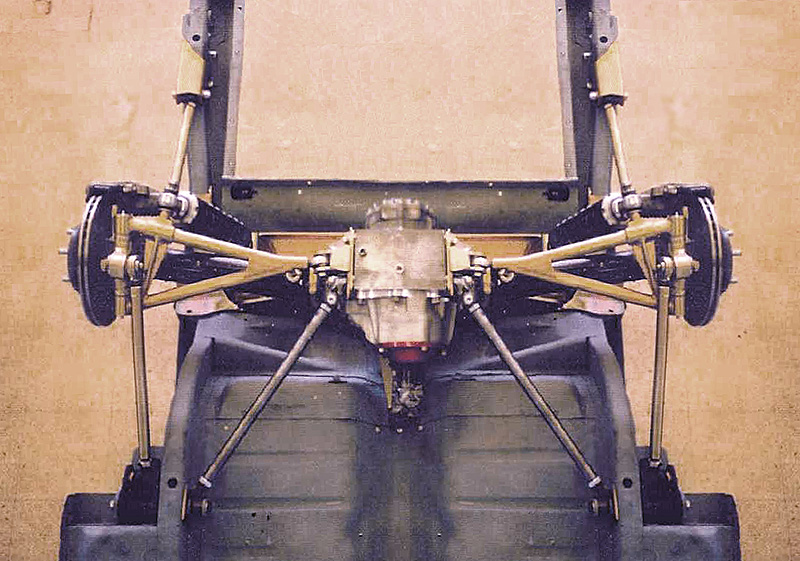
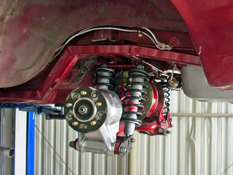
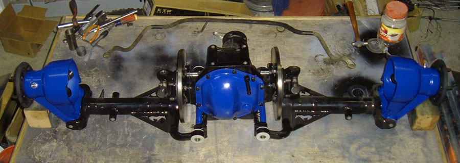
Hey guys i build custom trucks with air ride suspension and recently picked up an 83 jag IRS for a project.
Problem i have noticed is that it doesnt get much travel, about 8" just eyeballing it. The ujoints are binding up on themselves. Id like atleast 10" if possible.
I was planning on basically only using the diff, building new uprights and upper and lower control arms and using CVs. Has anyone done this?
Also what about brake upgrades? Id like to run vented discs. The factory stuff looks kinda feeble to me lol
Thanks guys, ill for sure post pics once i get going on it!
![]() Offline
Offline

Welcome to the forum!!!!
As I said in my email I do not know of a CV conversion kit. tyrellracing here on the forum knows a lot about drivelines and such and should be able to help you more than I. However I got to thinking about it and I know the later Jag cars as well as the t-bird/mark VIII use CV joints SO you may be able to use a modern half shaft. the only trick will be bolting it up to the diff as they are splined on both ends. I would check with your local driveline shop as well, they may have some good info.
As far as the brakes, if you upgrade to modern outboard discs you can get them in the thicker vented verity.
![]() Offline
Offline
Well the whole reason we went with the jag rearend was cause the inboard brakes.....hahha
I just figured someone made a bolt on kit that upgraded the brakes, nothing out there?
![]() Offline
Offline

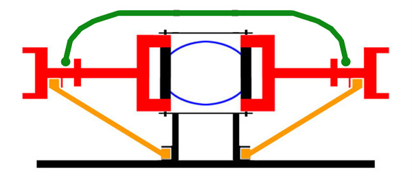
there is also an inboard disc kit. It uses the stock calipers and requires a spacer between the two halves, it also requires some grinding to the wishbones. here is some more info on the subject.

![]() Offline
Offline
I think i found that article in my digging. I was hoping someone had a kit ready to go, more work it looks like lol
As it is the ONLY part im gonna be using is the diff itself. Rest of it wont work. Im gonna have to narrow it and i think the factory control arm setup is kinda crazy. Im looking at using fullsize chevy pickup 4x4 hubs and building uprights. Then attaching them to the diff with custom built upper and lower control arms that attached directly to the frame.
Im also thinking about selling the whole jag axle and getting a tbird IRS that uses CVs stock and maybe doing inboard brakes on that.
Im not sure what to do just yet heh
![]() Offline
Offline

Slammy wrote:
Im also thinking about selling the whole jag axle and getting a tbird IRS that uses CVs stock and maybe doing inboard brakes on that.
That's what I would do in your situation. Especially since you want a separate UCA beside the half shaft and you want the CV joints. The hard part about going with the T-bird it's making the discs inboard. I believe the axles float so how would you attach the rotors??

![]() Offline
Offline
Daze wrote:
Slammy wrote:
Im also thinking about selling the whole jag axle and getting a tbird IRS that uses CVs stock and maybe doing inboard brakes on that.
That's what I would do in your situation. Especially since you want a separate UCA beside the half shaft and you want the CV joints. The hard part about going with the T-bird it's making the discs inboard. I believe the axles float so how would you attach the rotors??
Ahh yes the floating axles, thats something i recently learned about CVs. The axle shaft floats in there doesnt it? I would imagine that depending on how much it moved in and out i could maybe get enough room from the adapter id have to make to convert to CV in the first place.
I havent looked at all this real hard yet, i have have to just ditch the whole idea but i hope not!
![]() Offline
Offline
Concours West is expert at Jag IRS in trucks. Non-vented, non-slotted rotors are fine for normal street use, but these guys can help you with brake upgrades, as well.
Visit their site and give them a call.
![]() Offline
Offline
Yea i actually emailed them before i bought the jag asking a bunch of questions and never got a reply. Their website sucks but i did see a brake kit on their site
![]() Offline
Offline
Well i got my CV axles bolted up to the jag diff! I designed and had some adapters made that allowed me to bolt front AWD chevy astro van axles and hubs right up. Now i need to work on spindles and control arms

Last edited by Slammy (2/15/2011 10:10 pm)
![]() Offline
Offline

those are sweet!!!!!!!!! Was it a lot of $ to have them machined up?? So what are your plans for spindles and control arms??

![]() Offline
Offline
Well it would have been $300 but apparently there was a miscommunication so we had to remake them. He made the first set too thin and they wouldnt work. We came to an agreement on $500 since he had to do them twice, sucks but oh well.
![]() Offline
Offline
Been busy as hell at work but was able to get alittle done this weekend. I had the hub jig plates cut last weekend and finally got them mounted up. I ordered a third CV axle since i had two that didnt match.
So today i was finally able to bolt all this mess together. 


![]() Offline
Offline

HI Slammy,
Great stuff, I have heard that the front chevy hubs from a late model 4wd will work.
I can't see relative dimensions on the picture and it may be a dumb question what is the new wheel travel.?
Ol48
![]() Offline
Offline
It will have 11" of travel, it will do 12" but i cut it down to keep the cvs from being binded too much
![]() Offline
Offline

Slammy, that is looking fantastic!!! I cant weight to see it as you fab up some of the other parts for it. What are your plans for the rest of it?? LCAs, trailing arms, shock mounts??

![]() Offline
Offline
Daze wrote:
Slammy, that is looking fantastic!!! I cant weight to see it as you fab up some of the other parts for it. What are your plans for the rest of it?? LCAs, trailing arms, shock mounts??
Yea i can finally start looking at spindles and control arms. Ill design the frame according to where i need the control arm mounts.
![]() Offline
Offline

HI Slammy,
Looking at the adaptor that you made, do you think a similar adaptor could be made for the hubcarrier end?
![]() Offline
Offline
ol48 wrote:
HI Slammy,
Looking at the adaptor that you made, do you think a similar adaptor could be made for the hubcarrier end?
What are you wanting to do? I dont see an easy way to do it, no but anything is possible.
![]() Offline
Offline

HI Slammy,
I'm building a custom chev48 IRS, I have looked at most options. Heidts kugel etc. but all of these are at premium price.
one of the option that I'm quite interested in is from team321 www.team321.com
this approach is fairly cool. and uses a standard ford lincolm pumpkin and standard S10 hubs with custom A Arms and coilovers.
I was interested on building something similar using a Chevy Camaro lsd diff. Biggest issue was manufacturing the hub carriers. Hence why I went out and purchased a Jag IRS.
The biggest issue that I'm finding with the JAG IRS is that there is a lot of searching required to find the right ratios, LSD , upgraded rear brakes, bearings etc, lets face it these things are over 20 years old and technology has certainly moved on.
My plans is/was use a camaro diff centre with CV's and mate them to the Jag hubs using a similar adaptor to yours, or see if the s10 hub carriers can be fitted into the Jag hubs.
I will be measuring this combo over the weekend.
Last edited by ol48 (4/07/2011 6:34 pm)
![]() Offline
Offline
You must be talking about the new camaros with the IRS? That would be a better choice than a jag IRS id say. The only reason i used a jag was cause the inboard brakes but there are plenty of other IRS to use.
As for changing the hubs, the biggest problem i see is with the spines. Thats why i am using hubs and axles off the same vehicle.
basically it sounds like you want to do the exact same thing i am but you need a 5x 4 3/4 bolt pattern.
Id use a 2003 S10 blazer 4x4 hub and cv axles. The axles are different sizes so id order two of the same depending on what track width you want. Hopefully the assembly is too narrow and you can make adapters like i have but make them thicker to get the track width right.
Then you can build spindles and control and all that jazz.
You could also just get a complete IRS and redrill the hubs or use adapters, that would save a TON of work
![]() Offline
Offline

ol48 wrote:
I was interested on building something similar using a Chevy Camaro lsd diff. Biggest issue was manufacturing the hub carriers. Hence why I went out and purchased a Jag IRS.
The biggest issue that I'm finding with the JAG IRS is that there is a lot of searching required to find the right ratios, LSD , upgraded rear brakes, bearings etc, lets face it these things are over 20 years old and technology has certainly moved on.
As far as the ratios and LSDs if you abandon the Jag parts and go Dana 44 finding the correct parts are a piece of cake. The brakes are a different story. the Jag calipers are IMHO goos=d ones, and being a two piece unit they can be expanded to accommodate bigger rotors. problem I am having is finding a bigger rotor that I can make to work in this application.

![]() Offline
Offline
You already have the Astro hub on that axle, what you need is an upright. Same 3 bolt pattern as the hub look at T-Bird setup or make a triangular one like Rorty Locost setup. Couldn't post a pic but here is the link showing the upright,his is 4 bolt pattern but you get the idea.
Last edited by 260MGB (4/29/2011 10:21 pm)
![]() Offline
Offline
260MGB wrote:
You already have the Astro hub on that axle, what you need is an upright. Same 3 bolt pattern as the hub look at T-Bird setup or make a triangular one like Rorty Locost setup. Couldn't post a pic but here is the link showing the upright,his is 4 bolt pattern but you get the idea.
Yea im gonna build uprights simliar to that. The one problem im having is the control arm geometry and the dynamics of whats best for a street driven vehicles. Ive read 1.5 degrees of camber gain but i also need 11" of suspension travel. Im gonna have to really sit down and look at this.
![]() Offline
Offline
Slammy, I love what you are doing with the CV's ... I did some simulations for Daze a while back using a CAD package called Solidworks. I used the stock lengths from a 69 XJ6 and calculated the camber gain through 10 degrees of travel up and 10 degrees down, then did a second calculation using Daze's length on his unit. The numbers were interesting. Starting with the half shaft at zero and camber at zero ... at 10 degrees up the camber goes to -1.83 and travels 2.54 inches. At 10 degrees down the camber goes to +0.79 and travels 3.15 inches. This is a total of 5.5 inches of travel which is half of what you are trying to get ... the camber gain at 11 inches is going to be interesting to say the least.
![]() Offline
Offline

JOE!!!!!!!!!!!!!!!
Welcome back, your comments have been missed. How is your project coming??

![]() Offline
Offline
Joe wrote:
Slammy, I love what you are doing with the CV's ... I did some simulations for Daze a while back using a CAD package called Solidworks. I used the stock lengths from a 69 XJ6 and calculated the camber gain through 10 degrees of travel up and 10 degrees down, then did a second calculation using Daze's length on his unit. The numbers were interesting. Starting with the half shaft at zero and camber at zero ... at 10 degrees up the camber goes to -1.83 and travels 2.54 inches. At 10 degrees down the camber goes to +0.79 and travels 3.15 inches. This is a total of 5.5 inches of travel which is half of what you are trying to get ... the camber gain at 11 inches is going to be interesting to say the least.
You did this using the jag design with the lower control arm only? It is my understanding that an upper/lower control arm setup has MUCH better camber control, its just a matter of getting the lengths just right and the mounting points exact. Thoughts?
![]() Offline
Offline
Yes I did use the jag design with the LCA. I don't know as much I would like about the details of CV joints as they move through the motion of the suspension. Pivot points however are relatively easy to analyze once you know the lengths and positions. 
Here is the model that I used. The pivot points for the half shaft are based on the length from eye to eye and the same for the LCA. The positions are taken directly from the center section and the hub.
In your situation everything is pretty much unknown and can be set to anything you want which makes it more difficult (as you already know). A couple of things you do know however ... the overall length of the unit, the lengths of the CV, and the pivot points of the CV. Imagine that we create a new model for you (I would be happy to do that) and we start with just the CV and move it up and down 11 inches or more. Then we dial in whatever camber gains and losses you think you might like and then calculate the lengths/positions of the upper and lower control arms
With SolidWorks if there is a conflict the software will identify where it is. It will probably take several iterations and maybe a couple of changes but I am sure we can get you close to what you are looking for.
Last edited by Joe (5/05/2011 5:24 am)
![]() Offline
Offline
Man if you would be willing to help me figure out this geometry id really appreciate it . Once I know what I need I can really get going on building parts.
I'll get you some measurements I have at the house later
![]() Offline
Offline
My pleasure ... should be fun.