
|
|
|
 |
 |
 |
You are not logged in. Would you like to login?

![]() Offline
Offline

Racing Aspirations
I found this simple to use interactive calculator. Problem is it's metric and it's not fitting this net book screen. Conversions will be needed. To use, drag the yellow arrowed corners to correct dimensions. then drag the hub blue arrow up and down to articulate .
I substituted mm for inches. 20 mm equaling 1". A length of 18" would equal 360 mm, 12 = 240. It's the ratio's that are important. I also changed the field to a 1.5 scale.
I needed to go full screen to see the numbers and the graph, F 11 key.
Last edited by Ralphy (1/16/2012 8:49 am)
![]() Offline
Offline
These are facts I think about any Double Wishbone design.
You can't retain the same ratio when narrowing, When you narrow any amount, you will have to remove equal amounts to both the bone (LCA) and the half shaft (UCA). You can't remove more from either! In percentage the shorter link will lose a higher percentage amount.
There are three factors that control the amount of camber.
1. Ratio, the difference of length between the LCA and UCA.
2. Timing (position) of the two links, UCA and LCA.
3. Distance between the LCA and UCA.
1. Ratio, the greater the percentage of length between the LCA and UCA, the higher the camber effect.
2. Timing, if your UCA is flat level 9:00 and the LCA is at 8:30. This will have a greater camber curve then if both UCA and LCA are equal at 9:00 (parallel). This can also be expressed in ratios. Inner vs. outer.
3. Distance, the greater the distance (vertical) between the LCA and UCA the less camber you will have. This would be calculated as an average. Vertical distance of the inner pivot plus vertical distance of the outer pivot divided by two.
Also, the higher the arc as your (static position) starting point, the greater the camber curve will be. This pertains to jounce. Jounce is the important factor, since this will be the loaded (dominate) side of your chassis. Camber is progressive not linear. This \ / will have a higher curve than this ---- ---- and so on to this / \
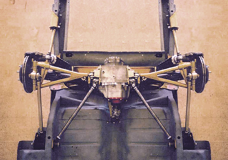
With a Jag or early Corvette IRS, the half shaft is the UCA.
The travel distance of your suspension is pretty much a constant. Typically when you modify the geometry you want to know the camber curve before changes, camber per inch of travel. Then after modifying, camber per inch of travel.
Last edited by Ralphy (1/16/2012 8:52 am)
![]() Offline
Offline
Ralphy:
When making such braud form statements on control arm ratios. It helps to step back and realize that the XKE was where the original design began. The XJ series IRS we have been beating to death is the modified version. It was stretched in width for use in a sedan. There fore since the XKE was the performance car that was produced years before the XJ . The XKE geometry is much closer the narrowed version that Daze made than it is to the XJ6. Bottom line the XJ6 was a compromise created on the same or similar hub carriers and differential but longer LCA and half shafts. So arguing about the ratios is laughable.
In a nut shell, The XKE is the parent design. The XJ is the compromised and revised design that used the same vertical separation of Half shaft and LCA more to simplify manufacturing and reduce costs than for any performance gain.
![]() Offline
Offline
tyrellracing,
Respectfully your missng my point. I'm trying to create a base line for anyone who decides to modify and install an IRS. Those 3 facts I posted I believe mathematically are true.
There are three factors that control the amount of camber.
1. Ratio, the difference of length between the LCA and UCA.
2. Timing (position) of the two links, UCA and LCA.
3. Distance between the LCA and UCA.
From what I see in your post your saying they (compromised) the design when they extended the same unit from an XKE to a XJ. But remember they widened it to fit in a wider bodied car. A wider bodied car that has body roll of 1", pitches less in angle. So it does not need as much camber, right.? So is it really compromised as you say? I rough graphed the Jag and Vette in another thread heavily exaggerating the length for visuals. Some here think as you narrow the camber decreases. however the graph shows the opposite. This is good because as you narrow you need more camber in a narrower bodied car.
Read this I posted last night.
OK, this exercise for me was to tell where I was going when my install was done. The two rough sketches C3 and Jag. Second lower view is at half length on the lower link in each sketch. What I see is that as I narrow an IRS, the camber increases and the roll center goes up. Changes are in red, total angle is not inserted. As I said this is a rough sketch. The points are fairly close. Notice how the Instant Center decreases by a fairly large amount. Raising the RC diminishes the need for as heavy a sway bar. Since a higher RC creates less roll. The upward motion in red is equal in both views.
So you narrowed the IRS and you did it for a reason. More than likely it came out of a wider bodied car. So does the camber really increase? Being that the body you have is narrower, 1" of body roll will give a greater angle. So now the added camber per inch is needed in a narrower car. So all the geometry should come back to a pretty good formula for the car you have. You will however, still have a higher roll center. Narrowing, mathematically works out good. Moving the inner LCA pivot lower, will even bring the RC back on a C3 or I think a Jag.
So bottom line, we are now saying the same pretty much. Some of my points have changed. But I was only trying to find a base line for any conversion. I have said and retracted some of my statements. I had thought RC's would lower when you narrow, but the opposite is true, based on what I see after graphing. But I think when done we can have a baseline of facts when doing a conversion. It would be nice to have a page listing facts on conversion. Factual information for any one who would stumble over here.
Last edited by Ralphy (1/18/2012 10:15 am)
![]() Offline
Offline
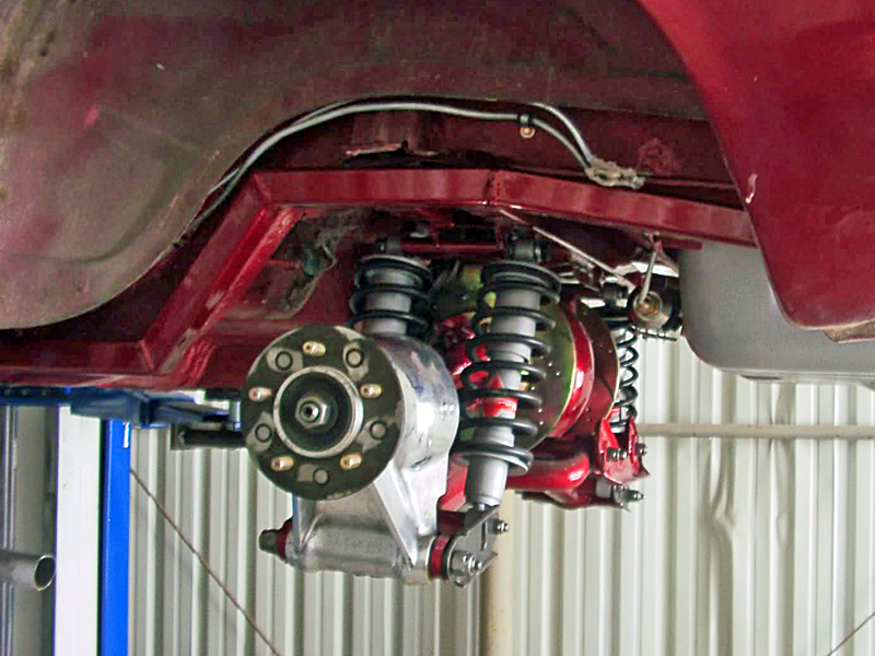
One step further, my thinking is that as you stuff a wider tire under your car, inside the wheel wells. Typically you would need to adjust the width of the IRS. Because of clearance issues between the control arms and wheel/tire. This would cause real increase in camber. That may, I say may be where 94cobrasvt is going. However he said his Fox body is narrower than a more modern Mustang.
I think I may be dealing with this on my C3 IRS having 10" wheel/tires.
Last edited by Ralphy (1/18/2012 10:16 am)
 1 of 1