
|
|
|
 |
 |
 |
You are not logged in. Would you like to login?

![]() Offline
Offline
The amount of roll steer is at its worst minuscule. If it exists at all. Roll steer is by definition is bump steer at the rear suspension. As such, can be measured in the same manor. The change in toe does exist but in such a small amount I feel it is sum what a non issue.
Starting from 3in. below, and moving up to ride height there is less than 1/32 change in combined toe. From ride height to 3in. above there is 1/16 toe in. This all occurred in the last 1.25 in.
I cannot in all honestly feel this from behind the wheel and most of all it would be roll under steer. If it went to toe out above ride height or when the suspension was compressed it would have been roll over steer. That was not the case.
BTW I just realized that my notes in my log book were taken from the wheel in relation to the car. Not the car in relation to the wheel. To clear up any misunderstanding: The toe in began to occur when the suspension was compressed more than 1.75 in past normal ride height
![]() Offline
Offline
Ralphy:
Have you ever driven a 289 Cobra, Ace or a Zagato? I have . samples of all three. Many times. They actually handle and drive unbelievably good. Even with the skinny bias ply tires that were on the ones I drove , they gave the driver a sense of confidence and were quite predictable. You knew just how far you could push them before the tires would break loose. Then if you knew how to drive a corner with the throttle you could take it to the next level and push a drift with confidence. The cars were ridiculously light and responded in a predictable manor. They felt down right nimble and were so incredibly neutral that the only way I can describe the way I felt driving them hard was confident. This type of suspension was crude and the leaf spring playing a dual role as a weight support and UCA. would seem to flex too much. However the less than 2100 lb weight of the Zagato and similar weight of the Cobra, they did not exceed the limits of this design. For those who do not recognize the Zagato,This car was built by AC cars of England. The Zagato was a hard top and the Ace was a roadster but aside from that they were the same car. The Ace looked identical to the 289 Cobra but had a different nose. Underneath the skin the frames and suspensions were identical. The engines in both the Zagato and Ace were all aluminum 6 cylinder Bristol aircraft engines. The roof line of the Zagato was like a fast back with lumps in the roof to accommodate the drivers and passengers heads similar to the late model Corvette's roof line.
Now when the 427 was to be installed in the Cobra Because the Corvette was to be equipped with the ZL1 aluminum 427 the following year. Planning ahead they knew they had to re-designed the chassis and suspension before combine the two. The leaf spring design was abandoned entirely. Heavier tubing was used in the ladder frames and a heavy duty suspension with coil overs were used at all four corners among many other changes. In short, the 427 was never installed in a 289 type car. The rear suspension that you posted with out a leaf spring was a common design for the time period. It was not invented by Klaus. It was used in many different F1 cars since the late 50's and everyone that used it fought the inherent quirky handling it provided. Lotus and Ferrari both struggled with this same design and were able to solve some of it's flaws.
BTW its roll OVERSTEER that was the hated part of that type suspension. Nearly every factory IRS sold to the public had some roll under steer designed in for a safety factor to novice drivers. The eary 427 Cobras had serious issues. They took a light little 289 sports car that the men who raced them loved the neutral feel and even though they had less horse power they could do circles around the competition. Then they added a engine designed as a truck power plant, added 500lb steel to the frame and suspension, and a ill handling IRS. What they made was an over weight pig of a sports car that was fast due to shear horse power and little else. The427 Cobra wasn't undrivable, rather when compaired to the 289 it was a tank. It had none of the predictable neutral steer characteristics the 289 car was known for. It was no longer nimble. It required an entirely different style of driving technique from the 289. The drivers relied on the throttle to create the neutral drift effect and due to this was totally unforgiving to driver error. It no longer had a designed in neutral steer feel what so ever. None of the light .nimble neutral feeling little sports car remained. It became a hairy chested brutus like monster in weight and feel. The races they won with the 427 were the result of guts and lots of hp. not superior handling!
Last edited by tyrellracing (1/21/2012 4:13 am)
![]() Offline
Offline
Now I may rant about the FE powered Cobra but I know the deficiency in design can be re engineered to a 21 century level of refinement. The only limitations are Time, Money and what the designer/builder can imagine.
If car manufacturers really wanted to produce max effort suspensions in feather light cars with even modest horse power, they could. The problem is the average american new car buyer cant drive. If in doubt, go out and watch traffic on a snowy day. LOL
![]() Offline
Offline

TR,
That's some really good feedback and writting in those last three posts to me. As far as your forward lower link. What I am trying to say is that if that link given the same angle but shortened to half length say. Attaching to the chassis one foot further back or so, would tend to give a very less favorable cornering effect. I like the fact it goes that far forward.
I think that another point not mentioned or the name does not imply with anti squat. That when braking the same angles that create anti squat, help hold the rear of the chassis down. Aiding the anti dive of the front end in a braking condition. Although the mass of an IRS sprung weight is not a lot. However, it's more.
Ralphy
Last edited by Ralphy (1/21/2012 7:35 am)
![]() Offline
Offline
The $64.00 question I have, the upper reversed trailing link. That Sasquatch, red headed step child, freak of suspension, oddity! Really has my curiosity. At what angle is this link sitting static? With a solid axle, acceleration forces should push on this link But the IRS would pull right. How well does this link get along with the whole............ IRS?
Ralphy
Last edited by Ralphy (1/21/2012 8:08 am)
![]() Offline
Offline
That's what a kinematic study is. You incrementally cycle the suspension when drawn or construction model in 3d. The LCA controls the toe setting on the free body diagrams. The way to think of these interrelationships is like the bmw or datson 510 trailing arm where the arms are angled away from parallel with the center line of the car and will have a large camber and toe change with wheel travel. Most people who race these cars make their suspensions very stiff to hold them in as close to ideal as possible. The change is so dramatic that very little wheel travel is required before the tire grip begins to deteriorate from incorrect camber and or toe. Your roll steer would have all the same change in toe with wheel travel as the trailing arm and I am failing to see a benefit.
A year ago I downloaded some images of a front full race suspension. I then used the images to scale drawings copied from Griggs racing. They are rather proud of their suspension packages that can make any year mustang produce 1+ lateral G's. They show a Griggs stang cornering at 1.5 G's on DOT tires. The GR350's are available for 65-70 . This kit goes for over$ 9000.00 for the front. Google GriggsRacing and click on his photo gallery. Look at the 65 fast back and its LCA mounting angle I made a copy of my own. I have a spare 67 mustang nose section with this copy installed, level, and aligned . I have been doing all this testing off the car because I have to cut off all the original motor and lower suspension mounts to install.. The primary concerns are measuring bump steer , Camber gain,and caster change. This project was put on a back burner at the end of last summer
![]() Offline
Offline
Ralphy:
All I can say about Anti- squat/dive is you hit the nail on the head. The design that lifts the rear under acceleration will pull down under braking and will be as effective at one as the other. Doing so is the proverbial two birds with one stone. However when the brakes are mounted outboard the rotational force on the K.A. linkage has an even more dramatic effect on the anti dive. I still have my brakes mounted in board so I do not fully take advantage of this. I was torn between unsprung weight and anti dive. Reduced weight won.
The K.A. suspension modifications I made to the Jaguar IRS had virtually no effect on the ride quality or the lateral grip. It only stopped the wheel hop.
Wheel hop aside, I noticed no difference at all in how it performed so If I have built in roll steer its too small to be concerned with.
From a standing start, it is slower than the old 9 in.
Last edited by tyrellracing (1/22/2012 6:15 am)
![]() Offline
Offline
As to your $64000 question. I have the car on a center lift with the wheels at full droop. This gets them out of the way for painting. My best guess on the leading link would be between 25 and 30 degrees from the bottom of the hub carrier up to the frame at normal ride height. The trailing link goes down from the top of the hub carrier to the frame aprox. 10 degrees The live axle links were at a similar angle but to compair the two would be pointless. The live axle uses the rotational force equal and opposite as the force required to turn the tires to act on lever arms welded to the bottom of the axle tubes vertically 6 in. long. On an IRS all these loads are kept in control at the frame. none of it is applied to the hub carrier. With the live axle under acceleration the rotation force not retained by the leaf springs is directed to the frame just ahead of the spring eye. through the lever arm and link. The hub carrier has no rotational force to do this . The forward force is divided between the leading and trailing links. Since the trailing link attachment point is much closer to the axle center line, it gets more load then the leading link. The leading links upward force gets smaller every time I look at just what it does.
Last edited by tyrellracing (1/22/2012 5:46 am)
![]() Offline
Offline
TR,
I think Daze (Day) would love to see what you have. Because I think he is of the opinion that the KA would not work with inboard brakes.
As far as the angle, that makes some sense to me. If the rear link were opposite, it would reverse the effects of squat somewhat. However I was imagining it would be at zero degree static.
Ralphy
Last edited by Ralphy (1/22/2012 7:30 am)
![]() Offline
Offline
Its nowhere near as tough as Daze thinks! (when you have a big lathe)
The inboard brakes were a problem. Having rotors that were wider and 1in. larger in diameter only made that problem more severe. The solution was straight forward. Since the shape of the control arm makes little difference as long as it is ridged and holds all pivots in their assigned places. It can look like a pretzel with out problem. My solution was two fold, First My rotors may have been larger but they incorporated almost no off set. The rotor is directly over the companion flange and due to this further from the differential. This was also required for ducted cold air routing . I used Kelsey hays 4 piston calipers at the rear so new brackets were required. With the caliper further offset away from the diff.the mounting bolts are much easier to get to than the Jag config. The inner pivot requires a single heim. Since this CA supports the weight I used a 3/4 heim with a 5/8 hole. With the rotor relocated, I had an additional couple of inches clearance to work with but still wasn't enough to fit on center where I wanted it. That is why I offset the CA 2 in. forward of center. The CA has a kind of U to it just at the inner pivot. This is for rotor clearance. It works just fine and I will down load pic's as soon as I can.
Daze:
At the time I down loaded the images of my cross member I had all ready made the rotors, rotor hats, caliper mounts, and three different sets of LCA. mounts. I had also put a few hundred miles on the IRS trying to solve the issues I had described in post's at the time. I drove the car to work every day last summer with the K.A linkage in place. Satisfied with the mechanical aspects I decided to do the body work when the monsoon rain came at the end of Sept. The body work has been done since before last christmass. The car is totally masked off and currently free of oily finger prints. I plan on keeping it contamination free till the paint is done. It is still dismantled waiting for warmer weather to be painted.
Last edited by tyrellracing (1/24/2012 1:56 am)
![]() Offline
Offline
TR,
Judging by your postings you really do not know what the bump-toe/steer is doing on your car. If I'm correct, your wheels could possibly even be toeing out under bump conditions. Where did you come up with the proper offset between the front and rear camber rod at the upright to be applied, other than drawings? Did you set the front higher by inches or angles?
Ralphy
Last edited by Ralphy (1/23/2012 6:36 am)
![]() Offline
Offline
Here is the page on bump steer. Titled,IRS Bumpsteer
"At 2" of bump travel, the factory roll-understeer and bumpsteer were considerable - roughly 0.35 degrees of toe change at each wheel"
David does get a little crossed up in his explanation, here he contradicts what he had said previously. "(i.e., toe-in at the inside wheel and toe-out at the outside rear wheel)"
Then here he talks, adding over-steer when in fact his new numbers show a more toe neutral IRS. Which is what he does want. "The new toe-curve provides 'roll-oversteer' at the rear of the car."


Last edited by Ralphy (1/23/2012 6:06 am)
![]() Offline
Offline
phantomjock,
You got me going on this roll center height. I'm sitting here graphing a C3 half-shaft/camber rod geometry with a UCA. What I see is if you were to add a UCA the roll center lowers visibly. So when Pier built his design he also lowered the roll center. The IC moves way out!
Hmmm.......
Ralphy
![]() Offline
Offline
Ralphy
I have always used a surface ground 1/2 plate 24in. dia. I made this years ago on a Blanchard grinder with the 5 on 4.5 bolt circle. With my spring removed and sway bar disconnected I cycle my suspension with a floor jack while I use a hinge plate with a single indicator like the one shown. I took multiple readings of the toe on the rear after installing the K.A. links before I ever put the tires on. This is just part of my alignment regiment . I have a pair of old Hunter alignment heads with lazers installed for setting toe. I also use a longacre magnetic caster/camber gauge. At normal ride height I set the toe at .125 12 in. forward of axle center. .0625 per side. When the wheel travel went below ride height , the change in toe was less than .020. at -3in. Above ride height I observed readings that were additional toe in. Not out. The change in toe per side at + 3 was from .0625 to.095 toe in . The small amount of roll steer measured is not likely to play much of a roll in the handling as a whole. Especially when you stop to consider that the roll bars combined with the stiff springs together create a large amount of roll stiffness. If you were to try to bounce the front of my car with your whole body weight , you would not get more than 1/2 inch of movement. Some of that is spring but most is shock dampening.
The amount of body roll is so small that the 1.375 front sway bar pulls the nose down instead of allowing lean when cornering hard.
These are my observed readings. I dont think the theoretical method of determining roll steer is as universal as you have been led to believe. It may work with twin parallel leading links like the Vette has or with a more traditional linkage but it did not predict the results of the KA set up
I have no idea why, I just know my IRS never produced toe out as you predicted. In a nut shell it makes a very small amount of roll understeer!
I cannot feel .030 change in toe in the front, Can you? That would be less than the tread distortion caused by simply rolling. As far as the toe readings in the charts you provided. So those numbers mean nothing here because they came from an entirely different suspension. Wouldnt that be like saying motor homes are top heavy. your vehicle has four wheels there fore your vehicle is top heavy. The chart has as much in common with my suspension as a motor home! In other words you are trying to say that the readings I got cause effects I am not aware of? Just rolling down the road your tires distort more than .020 when they meet the road surface.
![]() Offline
Offline
I can only report what I have heard, so I have no real experience. However over at VetteMod and phantomjock probably knows Pier and his design. He (Pier) is able to dial in and out the amounts. When Pier setup his geometry he had reported that his early settings made his car wicked to drive. Way to much! He had to reduce the amounts of roll steer. I think he has maybe even done an about face in even trying roll steer at all. (Pier auto- crosses his car.)
Add to that Kenny Brown builds that setup above to remove roll-steer on the Mustang Cobra design. There must be something to it. And in performance suspension books I have read. Roll steer is out for a race chassis!
Also I never predicted your car to toe out. I only said the design could. If your two camber links were dead flat level. In this position they would give zero steer at first sight. But because this your camber rod is fixed at the inner point, coupled with the fact that your lower trailing link is angled, this moves your upright rearward under bump conditions, this would open or toe out the rear wheels under the bump conditions.I did not say this is what you have. To create a zero toe you will have to keep the front camber pivot above the rear. The more angled these two camber mounting points at the hub/upright. Would create more roll-steer from that point toeing in.
Conclusion: Roll steer is a nice feature on a street car. However to much can be a bad thing, it must be tuned.
Ralphy
Last edited by Ralphy (1/23/2012 8:55 am)
![]() Offline
Offline
Ralphy wrote:
phantomjock,
You got me going on this roll center height. I'm sitting here graphing a C3 half-shaft/camber rod geometry with a UCA. What I see is if you were to add a UCA the roll center lowers visibly. So when Pier built his design he also lowered the roll center. The IC moves way out!
Hmmm.......
Ralphy
Ralphy - I'll have to take some spare time ![]() and do a plot (BonesApart) of the C3 and then Pier's approach to it. Pier's is a bit more C4-like - dual TAs etc. Maybe even do a C4 for baseline comparison.
and do a plot (BonesApart) of the C3 and then Pier's approach to it. Pier's is a bit more C4-like - dual TAs etc. Maybe even do a C4 for baseline comparison.
I do like the idea of being able to design the possibility of :
The new toe-curve provides 'roll-oversteer' at the rear of the car. In roll-oversteer, body roll induced by cornering results in toe-out at the outside rear wheel and toe-in at the inside rear wheel - effectively steering the rear of the car around the turn. [from; ]
BUT, I'm afraid there would have to be some dramatic changes to really get the effects of all-wheel steering!
As a point in that direction - I am planning on adding tabs to the leading edge of my rear spindle uprights - strategically placed if I want to add the TAs later.
Cheers - Jim
![]() Offline
Offline
PJ,
Pier's setup is not a true double wishbone, yes. What he has done unlike the C4, instead of using a longer camber rod. He uses an equal length to the half-shaft. Then changes the moment, at the upright. Lowering the mounting point. So if he were to level out even the camber rod with the half-shaft. He would zero out the roll-steer.
Having the camber rod behind the half-shaft, to me, like the C4. To me the best place you can put it from a strength view. Again the C5, pretty bad azz! And I know that's what your looking for.
Ralphy
![]() Offline
Offline
Deleted
Last edited by tyrellracing (1/31/2012 5:24 pm)
![]() Offline
Offline
Well I will sift through your post later. But as of now I have to throw the bullshit card on you. I 'm thinking you have a visualization problem. Plus on top of that you resort to personal attacks and now it's my turn. I will show you why you are wrong. Plus I think you assumed I said the roll is created by the motion of the LCA. I NEVER SAID THAT! But it does move fore and aft. Your now saying KA has no clue. Because KA eludes to the increase in wheel base during jounce. Your continually looking for a flaw I posted so you can then post some derogatory sentence about me . Not once have you asked, how I arrive at a point. You just get personal. I'm done trying to be nice with you and your personal attacks. You started with emails to me.
You claim I have no understanding how the T5 works? Did you really read what I posted? When I say camber that's in camber rod, because that is what the single rod on the Corvette is called. "The more angled these two camber/toe mounting points at the hub/upright. Would create more roll-steer from that point toeing in."
You may want to wish this motion of your LCA (camber rod) away. However it is there. This is not however how the roll-steer works. It moves in exactly the opposite direction you want! You will need to vertically offset the two outer pickup points, just to overcome this unwanted motion that would cause toe out. Your Watt's links motion creates this effect, also moving your rear wheel back, which is a good thing. The toe-out of the LCA is what you get during bump or jounce. Moving rearward. Overcome again by raising the pivot point in front at the upright.
This is a discussion board, not a board to compete to see who knows more. The purpose is to get at real IRS answers. THE TRUTH! So if you see something I do not see excellent. I'm trying to understand these complicated devices. But really, cut the attacks. And wipe the egg off you face. LOL!
First you came after me when I tried to make the point that narrowing an IRS increases camber. Which I have not been proved wrong yet.
You have questioned the three factors I posted about a long arm short arm. Which I still believe to be true.
There are three factors that control the amount of camber.
1. Ratio, the difference of length between the LCA and UCA.
2. Timing (position) of the two links, UCA and LCA.
3. Distance between the LCA and UCA.
You said the 427SC has no toe-steer. Which I think, I demonstrated it does. Your last response finally was. "That makes sense now."
Now we are here at this point. And you write, "I found it difficult to believe that someone who seems to be intelligent to insist on such a blunder. "
*****************************************************************************************************************************
*Note: Parallel links do not create roll steer. They remain a parallelogram fore or aft.
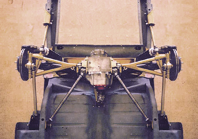
You will have the same if you were to take this C3 Dick Guldstrand design below and move the two camber/toe rods inner points together. The anti squat motion, moves the upright backwards under bump conditions toeing out. However if I rotated the outer ends, front up I can reverse the toe out condition. The more I raise the front outer pivot point vs. the rear, the more I go to a greater toe in or roll steer. I've looked at the KA's, T5 design, this one and others. Tried even to create my own design in my head and paper. So trust me I know this T5 pretty well.
One other factor to consider is if the upright rotates through suspension travel. This will also induce variations. This would be caused by the upper and lower trailing links position and length.
So imagine this. If I were to take this C3 design. Then move the front camber/toe rods inner pivot point forward, wouldn't I create toe-steer? The further forward I went with the inner camber/toe rod, the higher the toe curve would be? Looking something like this \ I Bump would move the lower points right and the top, the fixed chassis points \ I
Also on another point, if my trailing links were in such a position to rotate the upright clockwise. Wouldn't this create toe-steer? Changing the timing of the outer camber/toe link points, similar to Arning's T5? Haven't thought about this to much, getting really complicated.
*********************************************************************************************************************
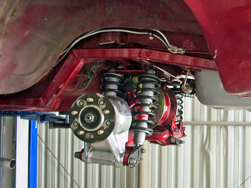
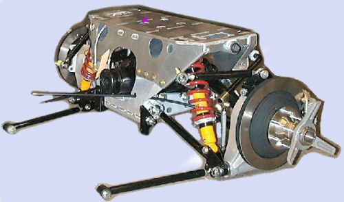
So wait a minute, why couldn't I use that same Guldtrand idea of two parallel camber/toe rods with a Jag differential with inboard brakes? Daze and I did discus this a little. The big difference between the T5 and C3? The T5 mounts the coilover to the camber/toe rod. The C3 mounts the coilover to the upright. How can you mount a coilover to a pair of totally independent toe/camber rods, IT CAN'T BE DONE!
WRONG! LOL!
Here is a view from ERA Replicas that manages to do just that. Put the coilover on the camber/toe rod. Why can't you achieve the same with inboard brakes? Still scratching my head here.
So many ideas out there, I'm still searching for my final compromise.
Last edited by Ralphy (1/24/2012 10:34 am)
![]() Offline
Offline
phantomjock,
When you mentioned the extended ball joints for front suspension. My thinking was this would not lower my CG, but now I see it does. Nice! The only negative effect I see maybe is this would lower my inner point of the UCA. Then maybe alter my bump steer. There are bump steer kits for the MII's.
Would you want to raise the inner point of the UCA? To bring the camber curve back a little?
Ralphy
![]() Offline
Offline
Adjustable UCAs- do the trick just fine for camber. And no holes to drill.
In my case I have those (SPC) and will use that feature to get the camber and toe set (fingers crossed!)
Howe makes the ball joints in 1/2 inch and 1 inch extended for the circle track folks - so there is a good bit of adjustment available that way.
Cheers - Jim
![]() Offline
Offline
TR,
For some reason it seemed you might have tried to estimate your LCA angle. And that you never had the opportunity to do an actual measurement. It seemed tome or I thought maybe you did not. That's why I asked or eluded to, to see if you did measure the roll steer. From the numbers you posted. I see you had app. 1/16 to 3/32 roll toe @ 3" bump. So if you started at 1/32 static toe plus 1/16 roll. Real roll toe would be .448 degree, almost 30 minutes. If I were to start at your high number 3/32 plus 1/32 static, total at 3" bump would be 1/8" or .596 degree total. Seems to be so small I know, but your falling right in line with that Mustang guy above. I find the numbers interesting because there are so few people who have been able to give any. There are only two I have seen now, you and that Mustang guy above.
.448 to .596 total degree at 3" bump? Or 3/32 to 1/8 total inches at a 12" radius app.?
Seriously, thanks for posting your findings (settings).
Ralphy
Just read your post again, you started at .o625 static toe per side. That's even higher, going from a minimum of 1/8" at 3" travel to 5/32" at 3".
What I have seen on the OEM cars. Such as the C4 IRS, bump or droop, you will have toe in. Verses your KA, which rotates the toe in the same direction, in-out, in regard to body roll. Going through a turn loaded side, toed in, unloaded, toed out. True roll steer! I know the loaded side becomes the dominant side. However I can't see how this doesn't have some negative effect on the C4, giving the KA design a superior edge. Maybe these OEM designs are the ones with the really noticeable, is it, snap steering issues?
T5, KA toe curve
So now let's go to another point you made. Roll steer was not started by KA? Interesting, but did all the other designs work like the C4 always toeing in, bump or droop? Did KA design a superior racing idea? Hmmm...........
Last edited by Ralphy (1/25/2012 7:06 am)
![]() Offline
Offline
PJ,
I'm looking up SPC. Are you saying that I should use an adjustable UCA and make it longer, changing the LCA to UCA ratio. Or are you still raising the UCA inner pivot? Or maybe both? LOL! Lost?
Looking like I may need to sell my MII aftermarket parts I bought. Got a steal on them anyhow.
Ralphy
Last edited by Ralphy (1/25/2012 5:14 am)
![]() Offline
Offline
Ralphy:
All your free body diagrams clearly started with three attachments to the vehicle frame that could never produce roll steer or for that matter even move with out breaking. Then the revised free body diagrams now clearly have two hinge points on each LCA that were out of parallel with the center line of vehicle . One of these designs you had labeled as ARNING. The free body diagram you drew had nothing in common with the T5 LCA. Then you went on to state that this diagram was how my suspension was to create roll steer even though the diagram was not anything like the T5. What was the deal with that?
I have a working copy of my suspension. I have cycled the thing many times during the alignment process. I wrote down all the spec.'s as I cycled the suspension in my log book. Both incorrect alignment and the alignment I approved. You do not have the benefit of this data to draw from, I do!
The leading and trailing link's do not respond in the manor you described and I have the data to back this up nor do they share any characteristics with the Goulstrand twin trailing arm you always want to fall back on as your example. Using angles that would be impossible to obtain on my car is a waste of time. In reality it still proves nothing.
Separation of my spring s from the LCA was to enable me to cycle the suspension with a jack. How would you measure all the data with them in place as easy any other way?
My example being : From a side view it would be impossible to make a Vettes wheel travel in a perfectly linear line. It is entirely possible with a T5. All I would have to do is replace my hub carrier. with no other changes. This is the fundamental difference you choose to ignore. No matter what direction you move your links , The twin trailing arms will always follow the arc path around the anchor bolt by the link length no matter what angle you move them to.
The T5 for comparison, can be made to curve forward, rearward, or perfectly linear. with out moving any link points what so ever. All I would have to do is move the position of the axle on the upright. This cannot be done with the Goulstrand . This is a quantum leap away from twin trailing arms and why all your spastic moving of links to non align able positions has no real meaning. Yes the designs can be changed to the point it no longer can track down a road. Where is the point in that.
The T5 does not have a Camber rod or a toe rod. It has a lower control arm. A toe rod usually connects a steering arm on the rear of the upright to the frame near the diff approximately the same length as the LCA so bump steer is not produced like the designers of the Goulstrand did on the Fiero Another poorly designed IRS from GM. There is no such thing as a Camber rod! Camber is the product of the upper and lower control arms on the upright. Neither one can take be responsible for camber with out the other. That's common sense!
There is little to be gained through discussing relocating the links to positions that would not allow the suspension to be aligned. That is a waste of time. Once you have moved the pivot points on a T5 or a Goulstrand you no longer have either. The fundamental part of each design is its geometry. Once you significantly alter it you no longer have a Goulstrand,.
I have my log book with my notes from the last 25 years. This includes my real IRS with all my drawings, alignment spec.'s. Not something I down loaded off line that some one else owns.
My notes are from my real car that I own and can walk out to my shop, put a key in it and fire it up. You don't appear to have any running examples of your roll steer design. I have yet to see anything you downloaded that you own. Even when you needed to provide a image of your car you posted a image of some one else s that was made by the same company as yours. In theory. I am sure you probably have a kit car.in pieces somewhere. . How many years has this cobra been a topic of discussion but never actually worked on. After finding this site I had a running Jag IRS in my Shelby in two months. It is easy to have a car that can do anything when you have not finished it . Who knows, at the current rate of completion it may never be a driver. Well I don't know that but it sure seems that way.
Going through my log book, I can see that even when the alignment wasn't right because the wheel wasn't centered in the fender it did not create toe out. When the camber was excessive the toe didn't change. The toe was measured with Hunter lazer alignment heads. These have a resolution of .005 inch. Each time I made a significant change I would cycle the suspension and take toe and camber measurements each inch. traveled. they were entered in my log book right then and there.
I guess the most important point I have to say is: I am writing about a running driving vehicle that I have had finished! The Jag Irs has been done since 2010,the T5 conversion has been installed for over 9 month. I drove it to work all last summer. with out any problems If the paint were done. I would be driving it daily still.
You have yet to explain how a vehicle that has such high roll stiffness that body roll in is nearly non existent could provide roll steer of any significance.
![]() Offline
Offline
I drew that diagram just for the point that you would see, it will not work TR. That was the point! In regard to the 427 SC. I will try and show you in another diagram what I see with the T5.
Because the lower trailing arm is at an angle during bump the wheel not only moves up, but also back. The LCA's inner point is fixed the outer moving rearward will angle the LCA rearward. So in order to offset this LCA angle a amount of vertical height difference between the outer pivot points would be needed to just create zero toe. Beyond that point would be where you get the roll steer.
Am I making sense?
Last edited by Ralphy (1/25/2012 7:37 am)
![]() Offline
Offline
I explained that I have Hunter alignment heads that use lazers to measure toe. They measure in thousandths not in degrees. However, converting to degrees would present no serious problem since I use trig every day at work. I am a machinist remember? Try laying out a 17 bolt circle on on an oval if you feel cocky. Dividers and trammels not allowed. Figure out the angles between each bolt hole when all the bolt holes are equidistant.
![]() Offline
Offline
I've worked as a machinist since 1974. Don't make me do that this time of day! To burned out right now.
Beside there are bolt circle calculators today. I know how to use trig! I started old school with a trig booklet.
Last edited by Ralphy (1/25/2012 7:42 am)
![]() Offline
Offline
I too have the toe curve graph. So what. Did you check that info with a working example? I did and It isnt the curve for Klaus Arnings IRS. I don't know where they came up with that graph but it doesn't describe the suspension I built nor does it describe Arnings. Therefore I don't care what they described it as. I have known this for 9 months now Again So what. Camber rod? LOL
![]() Offline
Offline
Your really just looking for a pissing match aren't you? All the time.
Grow up!
Yes, I questioned that chart also. Because I have never seen equal curves in both directions. However it is their chart.
Ego, one of the most damaging traits for man, and your full of it! Look that up.
And I see you shut up now that you can see the LCA does go to a toe out position at bump. LOL!
Ralphy 4 tyrellracing 0
Good bye!
How to find the 17 equal points on an ellipse? Easiest way, take it to engineering. Then the easiest solution to doing the job? Send it outside, job it out! In your case I would guess you took it to your brother. Your brother the NASA or aero space guy, whatever he is, showed you how. The one that calculated the dogbone.LOL!
Last edited by Ralphy (1/25/2012 9:27 am)
![]() Offline
Offline
Typical machinist attitude. We are some really messed up folk, including me! It's a product of the environment.
Some of the brightest blue collar people you can meet! LOL!
Seriously!
Damn, that was fun.
Give Mr. Ego A Chance
Last edited by Ralphy (1/25/2012 9:23 am)
