
|
|
|
 |
 |
 |
You are not logged in. Would you like to login?
![]() Offline
Offline

Not sure of the chart. If you were to narrow the IRS in order to get say 2" of wheel travel the half shaft would angle higher. The numbers seam to be going the other way. That is to say if your half shaft were 18" long and you moved it 10 degrees and the total travel in one direction were 2". A half shaft of only 9" in length would only move 1" per 10 degrees. The travel needed is constant, narrowing will increase the total angle needed to achieve the same travel.
![]() Offline
Offline
I think Joe's numbers are backwards. Again let's make the half shaft one mile long, 2" travel is a constant. The half shaft angle at 1 mile and 2" travel would have almost no angular change. This would also mean the camber change would be nil. Now make the half shaft 4" long and move it up 2", it (the half shaft) would be at a 45 degree angle and mass cambered. Narrower equals more camber.
What I see Joe has, equals less. Plus angle and total travel can't be the same at a shorter length. Angle has to increase at any given travel when the cord is shortened.
Narrowing increases the curve.
Last edited by Ralphy (1/13/2012 5:57 pm)
![]() Offline
Offline
joe put it in solid works and those were the numbers it spit out
![]() Offline
Offline
So if I pick up a 2X4 10 foot long at a 45 degree angle the end will be the same height off the ground as a 2 foot 2X4 at 45 degrees?
![]() Offline
Offline
In order to create the same height on a shorter length I have to increase the angle. He has angle and height as constants for different lengths, can't happen.
Last edited by Ralphy (1/14/2012 12:17 pm)
![]() Offline
Offline
the total travel was on mine not on both
![]() Offline
Offline
I will work on this tomorrow at work Day. The one thing I have not considered is the dogbone's inner pivot is inside the half shaft pivot.
![]() Offline
Offline
Make sure you look at that post I linked
it is the whole camber curve conversation, that will help. I wish Joe was still posting on the forum because then he could explain exactly what he did.
![]() Offline
Offline
LOL! Can't sleep, your distance between the dogbone and half shaft are fixed vertically right, at both ends? As you shorten the lengths the angle difference between the two increases. If the bone is horizontal this means your half shaft will be up at he wheel this angle will increase when you shorten Meanwhile the bone stay at it's point it's horizontal. This will increase the inward motion of the half shaft per inch. Trust me shorter equals more camber not less. I will show it on paper. Narrowing changes the moment between the two links. The ratio of length between the bone and half shaft increases as you get shorter.
Can't find a compass in the house!
Also it's no different than a double wishbone, equal length would equal zero camber change. The bigger the difference in length, will equal more camber. Half shaft equaling 12" and bone 18" gives a ratio of 66%. Half shaft equaling 8" and bone 14" equals 57%. And 4" X 10"= 40%. Going the other way longer, say 24" X 30" the upper would be 80% the length of the lower.
Last edited by Ralphy (1/13/2012 8:41 pm)
![]() Offline
Offline
its more complicated than that. did you look at that link I posted?? simply setting the 0º camber at various wishbone angles changed the camber curve. if something that simple changes everything so will adjusting the length. Like I said before these numbers were created by solid works so I have no reason to dispute them.
![]() Offline
Offline
Daze:
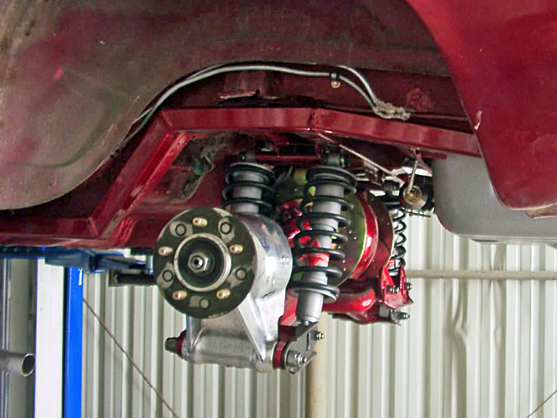
Yes the Jag irs has been in the car for some time now. I had it installed back when I was posting on the old forum. I put AFCO aluminum threaded body racing shocks on it with the stock springs. I was impressed with the improvement in neutral steer and control of the suspension however the shock dampening did not feel rite and the springs were too soft. The 408 stroker Cleveland I built is pretty stout and it can light up the rears with the live axle at 50. With the IRS, the wheel hop is so bad I would break parts if I were to do that. Even with the brake scoops hooked up to blow cold air on the inboard calipers, they were easy to over heat.
Far from satisfied I tore out the irs again so I could install the four piston calipers and vented rotors. I believe I posted it when I was still making Caliper mounts and hats . I re-valved the shocks to a 7/9 setting. Afco's are rebuild able and I have lots of spare pistons,springs and seals from other projects. I had a pair of King long travel coil over shocks that donated their springs to the cause. The King springs were 21.5 inches long free length so I cut them in half making four 10 inch springs. These were installed on the Afco's . The Jag IRS has linear antisquat built in with their LCA mounting brackets. I concluded that the mounting angle was causing the wheel hop.I thought the angle was too steep and was providing too much antisquat. I made new brackets out of 4140 with half as much built in angle. With all that complete , I hooked up the brake ducts and bolted it all back into my GT350. I liked the way it worked. The way the rear could continue holding when cornering hard on irregular surfaces was a massive improvement. The reduction in AS angle made a substantial improvement but didn't stop wheel hop entirely. The method of built in antisquat Jag used was torque sensitive and now with the reduced angle it just required more torque to make it hop. On both smooth and very rough surface the IRS could out corner the Live axle. no question about it.
I had a 31 spl. traction lock 9 inch with under ride traction bars and a watts link supported by custom springs I made with urathane bushings. By all rights a strong set up, On smooth roads it could really corner ( what I thought was "good") and it would hook up and launch with out wheel hop. On rough corners the unsprung weight was a serious impediment. Every now and then on a hard corner it would kick the rear out into a drift with out any reason other than the bumps in the tarmac. Some times fun, other times hair raising.!!!!!
I noticed a dramatic reduction in the ride harshness and road noise with the IRS. On the same hair raising corners, at the same speed and up, The IRS had no drama. Period! The roll center for the IRS is higher than that of the live axle. and is closer to the cars center of mass. This helps to reduce body roll by placing the roll center nearer to the same place that lateral G forces are applied to the car. This change in geometry is why I continued to try every thing I could think of to stop the wheel hop. Such a set up should not be hobbled with wheel hop.
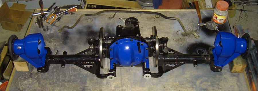
Months later...... I came across another XJ6 that was to be scrapped and was told I could have the rear for 50 bucks. Since I am a automotive pack rat at heart, I couldn't say no. After I got it home, I tore it down and gave my older brother one of the LCA,s for analysis and maybe FEA if he had time to do the digitizing . But that's another story.
Sorry, this is too long of a post. There has been a lot of water under the bridge since I first found this site and installed my Jag IRS and If I havent bored you to death and you want to read it , I will post the rest of my IRS learning curve.
![]() Offline
Offline
Ralphy:
I think you may be wrong and right. If you narrow a rear but retain the same ratio between the UCA and the LCA the ratio of camber change will be identical however when you compare a full width with narrowed the degrees of camber change per inch of travel will be greater on the narrow because you now have a large and a small rendition of the same thing. If you shrank one by 2% then to compare on an even playing field you would reduce in scale of measure by 2%for the smaller copy. In a nut shell, Daze put a smaller copy of a Jag IRS into his car than the standard size. Ratio wise there identical but the smaller IRS will produce more camber gain per inch than the full size because the same size inch is used to compare the two different size suspensions. If you change the ratio between the upper and lower control arm lengths you will change the ratio of camber gain regardless of scale
The shorter the upper is compared to the lower the faster the change in camber
![]() Offline
Offline
You can't retain the same ratio. When you narrow any amount, you will have to remove equal amounts to both the bone and the half shaft. You can't remove more from either! In percentage the shorter link will lose a higher percentage amount.
There are three factors that control the amount of camber.
1. Ratio, the difference of length between the LCA and UCA.
2. Timing (position) of the two links.
3. Distance between the LCA and UCA.
1. Ratio, the greater the percentage of length between the LCA and UCA, the higher the camber effect.
2. Timing, if your UCA is flat level 9:00 and the LCA is at 8:30. This will have a greater camber curve then if both UCA and LCA are equal 9:00.
3. Distance, the greater the distance between the LCA and UCA the less camber you will have.
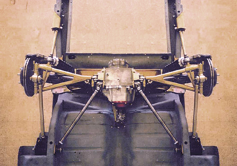
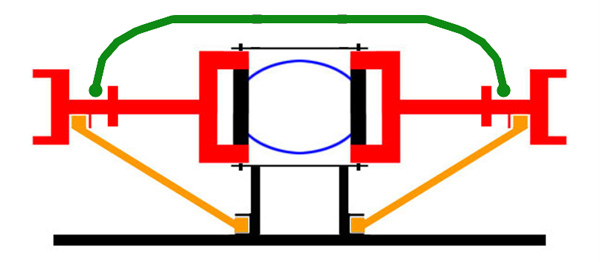
With a Jag or early Corvette IRS, the half shaft is the UCA.
Last edited by Ralphy (1/16/2012 7:27 am)
![]() Offline
Offline
Just the Facts, Mamm, Just the Facts.
I took a few moments to try and better understand the discussion you are having her regarding LCA parallel to the surface at ride height.
I take it in either case - you are planning on adjusting the inner point of rotation up - or - down to effect that?
I note that the Jag Dogbone has a distinct bend at the inboard end (at least in this picture). So I guess you are taking that into account? I ran a few numbers based on measurements from the image in the "BonesApart." Its an easy-peasy excel spreadsheet - and her are the graphic results plotted. Free - and works with Open Office too.
ANALYSIS:
The RC (for the given case) is located at 108 pixels (close enough to mm- for this case) - or about midway between the road surface and the inner LCA point of rotation. It shows little migration at 5 degrees of roll and likewise bounce/jounce of 50mm. [Plotted on the image for reference.]
If, however, you lower the inner LCA fitment location to be at the same height as the wheel mounting, you get a lower RC. Note the migration of RC that occurs. 
[Noted Chassis Designer - Len Terry, suggests a good first step is to fix the RC and minimize its migration as a good design starting point.]
You can reference the Thread on IRS Software - and follow the link and download the "BonesApart." Here is a screen shot of the data:
Remember- considering the entire suspension system Front and Rear, the Rule of Thumb seems to be:
The Rear RC should be about 2 to 3 times higher than the Front RC for a "good handling" vehicle.
Cheers - Jim
![]() Offline
Offline
PJ,
So my million dollar question. I know the roll center should not be the same. I did not know the rear should be higher. Does raising the chassis in such an IRS design improve the RC? C3 Corvette, am I better to have the half shafts level or sloped down to the wheels in rgard to RC?
Another question, I want to lower my car by one inch. I have a Mustaang II front end. There are 2" drop spindles made for the MII. My front LCA's are at a level position now. Would I be better to just lower what I have 1" puttig the inner pivot of the LCA 1" below the outer pivot point. Or add the 2" drop spindles and raise the car by 1" in relation, putting the inner pivot now 1" above the outer LCA pivot point? Another words which sloping direction of the LCA is better. I just know your to say it depends! LOL! ![]() This \ / or this / \ on the LCA's?
This \ / or this / \ on the LCA's?
Does a mechanial device such as the dogbone feel an impact because the inner mount is angled? Or is it really just pivot point to pivot point?
Last edited by Ralphy (1/14/2012 7:56 am)
![]() Offline
Offline
So my million dollar question. I know the roll center should not be the same. I did not know the rear should be higher.
Now - I've gone and done it! I read somewhere - that, "to mention roll center migration" - and suddenly you're "the new local suspension guru!"
The line between Front and Rear RCs forms the roll axis of the vehicle. The roll axis is "typically" tilted to the lighter - or lower (closer to ground) end of the vehicle. For a front engine - vehicle lower is usually forward. A Front RC should be from -1.0 inches (below surface) to about +3.0 above. Can't recall where I got that in my notes - but seems reasonable.
Does raising the chassis in such an IRS design improve the RC? C3 Corvette, am I better to have the half shafts level or sloped down to the wheels in rgard to RC?
The weapons school (AF TopGun) answer is; "It depends." Raising the chassis will also raise the CG, Not a good thing - necessarily. IF, the attachment points of the LCA & UCA were still be in the same position (relative to the surface - the RC would be the same and - a higher CG - maybe Not So Good. If however all migrated together, Pivot points up 3 inches, chassis up 3 inches, wheel attachment, etc - everything goes up 3 inches-Monster Truck it would be the same. If you move ONLY the Chassis attachment points Up on the UCA - the RC raises. Is that any help?
Regarding the C3 half Shafts. You've already made note they are the UCAs - unless other mods are incorporated (Jim's Giovanni, Drag Vette, etc.) A quick rule of thumb is - Raise the slant of the UCA toward the BODY raises the RC (holding all else equal.) Also, Raise the Slant of the LCA towards the body and get the same effect - Higher RC. SO, half shaft sloped down to the wheels (like using lower profile tires/smaller wheels- so ONLY the wheel attachment for the UCA changes) - vs horizontal - will lower the RC. That said the wheel attachment for the LCA stays the same. (But if you used smaller wheel tire combo - both would move down - right. )
Another question, I want to lower my car by one inch. I have a Mustaang II front end. There are 2" drop spindles made for the MII. My front LCA's are at a level position now. Would I be better to just lower what I have 1" puttig the inner pivot of the LCA 1" below the outer pivot point. Or add the 2" drop spindles and raise the car by 1" in relation, putting the inner pivot now 1" above the outer LCA pivot point? Another words which sloping direction of the LCA is better. I just know your to say it depends! LOL!
This \ / or this / \ on the LCA's?
Again setting the RC for front you want to establish first. My understanding (from my notes from a heap of reading) "Dropped Spindles do nothing for geometry. They can help/hurt bump steer. Alsocan present a problem with tie rod interference with the wheel. Better to investigate extended ball joints. You can raise the UCA pivot point at the wheel by 1/2 to 1 inch. Significant move in geometry. SCandC has the Howe Ball Joints for this purpose. Mark also does a lot of Mustang work too bet you could call him Monday.
Does a mechanial device such as the dogbone feel an impact because the inner mount is angled? Or is it really just pivot point to pivot point?
Pivot point to Pivot point. Check the Circle Track gear. They use bent UCAs so not to cut up the frame. Unless you mean for Anti-Squat/AntiDive?
Give the BonesApart a try. Simple to use --but a bit of a PITA to do the Imperial to Metric and back and forth - but good easy visualization - and fast too - free BTW. That's what my schedule is today - get the front RC sorted - one more time for the C3, then the rear. Then some modeling and get ready to order and cut metal.
Is your C3 rear end mounted up? Do you have the ref points - Inches fine - per the diagram I posted above - for BonesApart? I'll run those for you. Mine is all apart and no use right now - and I'm reluctant to spend a day putting it back together--only to take apart again. Diff is heavy!
Cheers - Jim
edit: Ralphy - I will add: That all the C3 references -- DO Say to set the half shafts parallel at ride height. Now that is on a C3 - and not a Cobra - So I'd do the calcs and see what gives. Also - Early on (1982-ish) John Greenwood frequently suggested to add 1/2 inch plate between the lower Strut mounts and Diff - lowering the inner pivot for the struts. (Elsewhere I've seen a reference to 1 full inch.)
Last edited by phantomjock (1/14/2012 10:30 am)
![]() Offline
Offline
Ralphy, I figured out why the chart is contrary to what you are saying 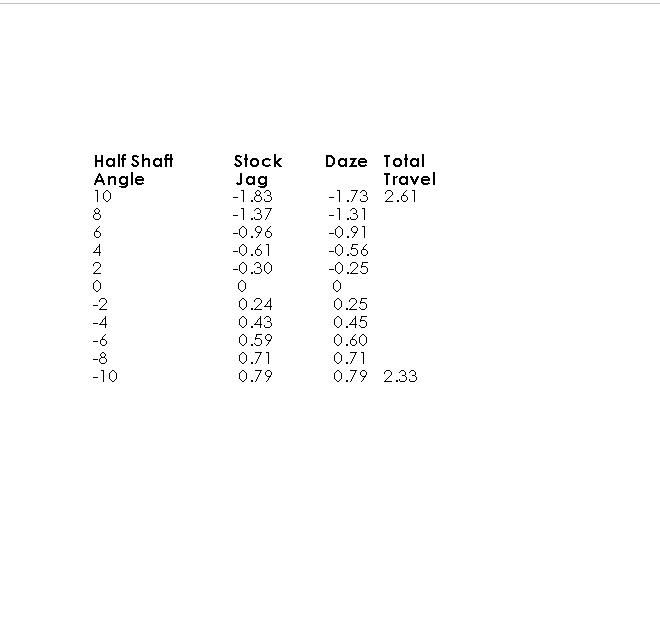
I have been pondering this for the last 24 hours. I could see your logic was correct, but I also new that the numbers Joe provided through solid works were also accurate. I came to the conclusion There both right.![]()
![]()
![]() you are correct as a unit narrows the camber curve becomes more aggressive, and his numbers are correct as well, but how could that be the the chart shows less camber than the stock unit. the answer is what the camber is based on, look at the left hand column, it is not suspension travel distance but rather wishbone angle. you said
you are correct as a unit narrows the camber curve becomes more aggressive, and his numbers are correct as well, but how could that be the the chart shows less camber than the stock unit. the answer is what the camber is based on, look at the left hand column, it is not suspension travel distance but rather wishbone angle. you said
Ralphy wrote:
That is to say if your half shaft were 18" long and you moved it 10 degrees and the total travel in one direction were 2". A half shaft of only 9" in length would only move 1" per 10 degrees. The travel needed is constant, narrowing will increase the total angle needed to achieve the same travel.
we are comparing the camber curves based on wishbone angle not suspension travel. it takes more travel on the larger XJ6 unit to get the same wishbone angles compared to my narrowed unit. As the suspension travels it gains either positive or negative camber depending on the direction. SOOOOOO even though the gain on the XJ6 unit is less than mine per inch of travel it is still having to travel farther to match the wishbone angle and that explains why the XJ6 appears to have a more aggressive camber curve ![]()
![]() Offline
Offline
Sorry, this is too long of a post. There has been a lot of water under the bridge since I first found this site and installed my Jag IRS and If I havent bored you to death and you want to read it , I will post the rest of my IRS learning curve.
bored you to death????? not a chance!!!! this kind of stuff to me is like a thrilling mystery or suspense novel to others so bring it on!!!! (might want to start a new thread though ) Also when you were posting before you had just started working on the vented rear discs, I would love more info. which rotors did you use, what did you do for hats, and so on. (again probably good as a new thread as this one has become a little cumbersome)
![]() Offline
Offline
Day that is what I was speculating. Joe punch the numbers with the same angle. If you read my posts at the top of the page I mentioned it. I rough graphed several lengths and as I shorten up up shows it clearly.
Jim I posted this as a reponse to something you had wrote.
Does a mechanial device such as the dogbone feel an impact because the inner mount is angled? Or is it really just pivot point to pivot point?
I think any angled changes mean nothing.
You wrote: I note that the Jag Dogbone has a distinct bend at the inboard end (at least in this picture).
This is pretty nice. Need graph paper? Type graph paper and you can find pdf files. Print as you need. No going to the store and buying 50 sheets.
Last edited by Ralphy (1/14/2012 12:38 pm)
![]() Offline
Offline
Day that is what I was speculating. Joe punch the numbers with the same angle. If you read my posts at the top of the page I mentioned it. I rough graphed several lengths and as I shorten up up shows it clearly.
but do you agree that Joe's #s are correct???
![]() Offline
Offline
Day,
His numbers are correct per angle of half shaft, but that is not what is important. Suspension travel is what I want to know, what is the camber angle at a specific amount of travel? Before narrowing and after. What was the camber at 1" and 2" of travel and what is it now. How much did it increase?The way the Jag is setup as you narrow the IRS the half shaft will be at a more inclined angle (static) the shorter you go.
Last edited by Ralphy (1/14/2012 1:21 pm)
![]() Offline
Offline
For U-joints to have a long happy life they must have some angle to circulate the needle bearings. According to Spicer, failure to provide this angle will brinell the journals on the cross of the U-joint and will lead to premature failure. If the Wicapedia pic were correct the suspension would have gained a reputation for rapid U-joint failure. It has not. The ride height that provides some angle to the U-joints with the LCA parallel to the road surface I believe to be the correct one. Everything I have seen and read about the Jag IRS supports this. As does the testing on my own car.
![]() Offline
Offline
tyrellracing - good call on the U-Joints - a factor no doubt.
For the movements of the arms and relative camber change, this sounds like an opportunity to model the hypothessis and then test it. Here is a sample of what you can check;
Note I have narrowed the JAG IRS 200mm (100 each side - and the Track as well -- kep the same wheel/tire combo).
I can't speak to the acuracy of my derived measurements - but if you can do better with graphpaper - have at it by all means. I have messed about with the String Computer approach - and find this quick and dirty little spreadsheet better and faster. I am less inclined to model a JAG IRS in SolidWorks - I haven't the details to do it right - and would not serve my mod efforts. But this is fast.
I held the chassis details constant - and the height of the wheel mounts and only decreased the width by 100mm each side. You see the results. I have shown only a 5 degree chassis roll, but you can also model the suspension through bounce and jounce -- 100mm each way.
I call attention to the graph on the side that shows the wheelcamber as well.
I hope you'll find it useful - but you know where to find it if you want to download and give it a go.
Cheers - Jim
![]() Offline
Offline
I've never heard of issues in regard to universal failure due to no angle with half shafts. The place it is spoken about is in regard to drive shafts between a solid mounted IRS carrier. The angle most often I hear is 3 degrees. The Corvette has been built for how many years . Do they suffer pre-mature failure? Early failure is not something I worry about with a weekend driver. It's not like most here are building cars to go 100,000 plus miles.
Jim, my monitor sucks I can't even begin to read that info! Or else I need a new eye exam.
Last edited by Ralphy (1/14/2012 8:14 pm)
![]() Offline
Offline
Ralphy - if you want - shoot me a PM -I'll send the jpgs - you can blow ém up! Not like a U Joint !!
Coincidently, there is a fresh thread over at DC on U joint rebuilds -- if interested:
To peek your interest, it starts off like this:
"Ok, I like doing this post because I get to show that great USA made NAPA zerk joint that cracked in 1/2 after 18k miles on a 350-300 336 vette. No hard abuse and it cracked shifting into 3rd gear at 3,000 rpm on the highway!
This is a pre-chinese junk part as well."
Its from gtr1999 - he is a well regarded wrench.
Cheers - Jim
Last edited by phantomjock (1/14/2012 4:38 pm)
![]() Offline
Offline
Learning cure continued:
I should back up a little bit here and describe the car as a whole. Back in 1982 I use to race motocross and was sponsored by Bob Lamphere. A local Honda dealer. One of the guys I was always banging handlebars with for the lead racing was a guy named John Hancock. As it turned out he lived less than five miles from me. His father built him a big practice track and I was invited to come up and ride when ever I felt like it. John and I became good friends and I was always hanging out at his place to ride.
His Father , Jack Hancock restored Shelbys and mustangs in his shop at home for a living. He always had an array of big block cobras and gt500's being worked on there. To a 19 year old like my self at the time this was treasure island. I had a 69 4 spd.Mach I at the time that I had installed a trailer hitch on it to haul my bike to races.
One day when riding my CR250 on their track I blew the trans up bad. Instead of taking my bike home, I went home and grabbed a spare bottom end I had with a cracked case. I then went on to pull my bikes engine, rebuilt the broken trans using the spare parts on the gravel drive in front of Jacks shop. Best of all I had it back together and running in record time. This did not escape the attention of Jack. He offered me a job as a grunt mechanic in his shop which included the ability for me to work on my car in his shop on my own time. For this I would have worked for free.
The next X-mas Jack purchased a 67 gt350 track car and gave it to his son for X-mas. Most kids would have been thrilled but John gave the gift a luke warm reception. He then went on to tear it apart, sand off the paint and leave the parts everywhere in his fathers place of business This went over like a turd in the punch bowl. John had lost interest and Jack wanted it out of his way. After months of this Jack and I moved the pieces out of the shop and on to a flat bed trailer. The car sat in the rain for another 6 months stripped to bare metal.
In a turn of bad luck, their house caught fire and burned to the ground. Disappointed with the outcome of events Jack decided to use the insurance money to buy property in eastern Oregon. The move was over 200 miles away and since John didnt deal with the car when it was in the garage he was going to have to find a way to move it to the new place himself.
Well he procrastinated and soon found he had no way or means to move the car. Meanwhile I was unemployed and heard through the grape vine the car was for sale. I scraped every penny I could by selling one of my dirt bikes and managed to come up with a little over two grand. I offered it to him for the Shelby but he turned it down. A few weeks later there was a knock at my front door and there he was accepting my offer. Believe it or not I hauled the thing home on the same flat bed trailer I had loaded it on with my 69 mach 1. The road home was steep down hill and all switch backs plus the trailer had no brakes. White knuckle the whole way. What I got for my two grand was a real 67 shelby gt350 race car with a 8 point roll cage that supposedly was a x trans am car. The thing had never been wrecked bad but had typical fender rub marks all over it. It was complete other than interior. It had a dual quad hp289 that was professionally built . a close ratio top loader, 9 inch with a detroit locker and four wheel disk brakes.
Great deal however I was broke, unemployed and wanted to drive this thing in the worst way. In my 19 year old brain the next best thing was to pull the 351 w and install the 289 in my 4 spd. Mach 1 and man was it a screamer. That little engine could do circles around the 351 all day long!!!!
It was about then my mom said that if I was going to live under her roof I either had to find a job or enroll in college. I started going to community college and the car was once again put on a back burner. I had however borrowed a sand blaster and removed the rust pounded out the dents as well as I could and sprayed it down with epoxy primer.
Two and a half years later with out a degree I quit college and started working as an apprentis machinist. I did the body work,removed some of the door bars so I could get in and out of the car with out being a monkey and painted the car red. I found the interior parts I needed at the April Portland swap meet and set up the car for SCCA production stock racing. The 9 inch all ready had the under ride traction bars and spring rockers as well as the watts link for lateral support. The shelby drop had been performed before I got the car and both upper and lower control arms had been boxed in. For braking it had Kelsey Hayse four piston calipers and 11.5 inch rotors at all four corners. The car had an adjustable per portioning valve mounted next to the drivers seat when I got it. It is still there today. I had put the HIPO 289 back in and was using it as a daily driver. It was relatively competitive but not due to cornering. It could make up lost ground on straight portions where I could kick in the spurs. I began to study the set up and determined the truck springs it came with in front were just way too stiff to work right. I purchased some 660 lb big block springs and removed one coil. Then I noticed the inner pivots for the UCA were shot. Who ever boxed the arms in welded the bushing housings in too. I solved the prob. by making my own tube steel control arms with bronze bushings. I then made a pair of lower control arms with 3/4 heims for both strut rod end and LCA inner pivot. I also welded plate over the LCA adjustment slot anddrilled a 1/2 inch hole so the inner pivot could not move then made a turnbuckle in the LCA to make alignment easier. Now the car was beginning to corner well. Then I came across a 65 Thunderbird parts car that had 13.5 inch rotors and large four piston calipers. It took some doing but I adapted the spindles to my mustang by relocating the steering arms. The ideal location for the steering arm that would produce zero bump steer just happened to be in space occupied by the wheel. Compromise is a terrible thing. If 18 inch wheels were available back then I would have done it right. The measurable bump steer was .250 inch but from the drivers seat was not an issue.
Over the years I changed the amount of drop of the UCA to 1.625 and fabricated another 4 or 5 sets of tube steel control arms in various sizes that were all longer than stock. This was all in an effort to find a better negative camber gain curve. When employed at Ore.Spring I had access to the stock mustang sway bar pattern and made several different thickness bars. The largest being 1.375in. I also changed the front shock mounts so I could use AFCO type adjustable racing shocks. This is when it finally dawned on me that all the changes I had made were being hindered by the fact that the springs were too stiff! Changing and refining the camber curve means nothing if the springs are too stiff to let the suspension move when cornering. You must have suspension compression when under lateral load for the camber curve to have any effect on suspension performance.
It was at this point that I decided to take a different approach. I converted the suspension to a coil over system that supported the car with the LCA. To do this I had to make another LCA that had a built in turnbuckle to align and would accept a MOPAR type thread in lower ball joint. The stock mustang lower ball joint cannot support the weight because it wasn't designed to do so.
Last edited by tyrellracing (1/15/2012 3:31 pm)
![]() Offline
Offline
Jim, that's why they invented MPI. I'm sure U joints do not go through any crack inspections after they're manufactured. Bad metal happens. I work in the aircraft maintenance industry, we have a handful of inspections, FPI, MPI, Eddy Current, X-Ray, Sonic. Parts are sometimes made with imperfections, sometimes they show from fatigue at a later date. It happens. We had an axle snap clean off a 757 rolling into the hanger. Let me also add this, a U joint works the most efficient at zero angle, period. Angle robs HP! Anyhow that sucker sure did crack big time. Right in the grease fitting hole.
I'm at home, this monitor is much better! Is your chart showing a 5 degree camber max? Er well about 3.75 change from (static) center?
Ralphy ![]()
$322.00

Ralphy - if you want - shoot me a PM -I'll send the jpgs - you can blow ém up! Not like a U Joint !!
Coincidently, there is a fresh thread over at DC on U joint rebuilds -- if interested:
To peek your interest, it starts off like this:
"Ok, I like doing this post because I get to show that great USA made NAPA zerk joint that cracked in 1/2 after 18k miles on a 350-300 336 vette. No hard abuse and it cracked shifting into 3rd gear at 3,000 rpm on the highway!
This is a pre-chinese junk part as well."
Its from gtr1999 - he is a well regarded wrench.
Cheers - Jim
Last edited by Ralphy (1/14/2012 8:17 pm)
![]() Offline
Offline
Phantomjock:
That is some damn fine software you got there. I want to analyze the Griggs copy soon but I still am shy of floor space. I built a small plywood platform then laid a 4x5 ft piece of 1/4 plate on it leveled it as best as I could and then put nose on it and got it close to level. I had got no further than setting up a control line to measure from and the snow began to come down. We are hunkered down for a snow storm approaching.. I hope the weather man is wrong again and this is only an overnight dusting of snow.
![]() Offline
Offline
hay 6 speed, not to poo poo on what you are doing because I am all about making a factory part better, BUT
Daze,
I never like to leave a question unanswered. You posed this question to me back on page 1 of this thread. The thread has drifted more into a geometry discussion of the Jag IRS which is fine, it's all related.
To answer your question, I'll work with the stock wishbone. I didn't want to get into engineering new pivot points and sizing of materials. Mostly a question of time.
Ken
![]() Offline
Offline
Jim,
I think I finally see how to calculate roll center!
Going by this, on my MII front end. If I kept the factory A arms and lowered my chassis, I would lower my roll center? So simple! And as you said, front roll center should be below the rear?
You know when I was a kid I could not grasp base two numbers. When I realized the answer, I felt so stupid. I was looking for something way more complicated, I just couldn't see the answer.
Last edited by Ralphy (1/16/2012 11:09 am)
