
|
|
|
 |
 |
 |
You are not logged in. Would you like to login?

 1 of 1
![]() Offline
Offline
on May 24, 2010, 9:03 am, Daze wrote:
OK, for those of you that have not figured this out about me, I am a thinker. I spend as much time, if not more, working on a project in my head than I do in my shop. By working a project in my head I can explore "all the options" (at least all the ones I can come up with) and their solutions. I design, and redesign long before I ever buy the steel or fire up the shop tools. Over all this attitude has served me well, but some times I over-think something and get bogged down in one aspect that really doesn't deserve that much attention, and I think I may be doing it again.
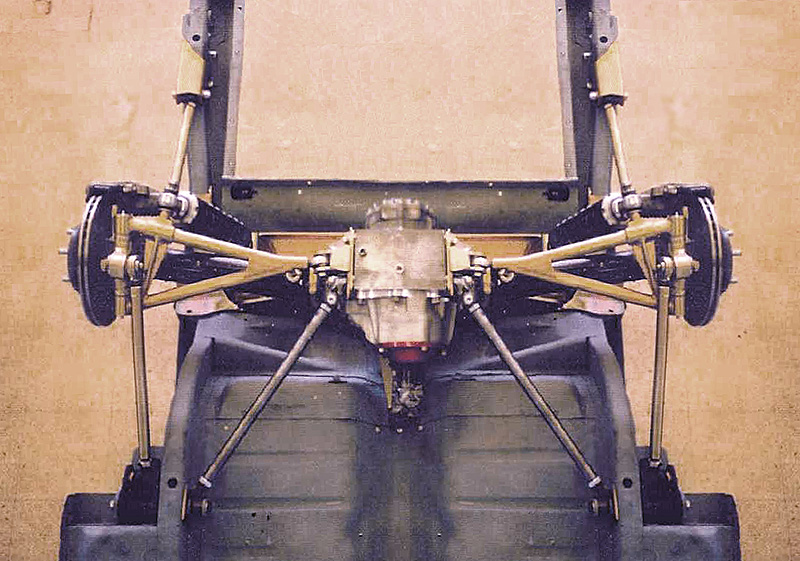
In an earlier post here on the forum, we looked at the debate over pinion angle. (joe, I would love to get your thoughts on the original post) At the time I was of the mind that you set the differential at the parallel angle to the transmission even if that means adding a slight tilt to the rear ends suspension travel, rather than setting it at 0º to maintain the correct vertical suspension travel.
I still feel that the correct pinion angle is more important than a less than vertical suspension travel, however the perfectionist in me wants both. I am trying to locate some XKE side brackets that connect the wishbone to the differential, because they are set up to cancel out a 6º pinion angle, but I have not had any luck finding a set for a reasonable $$. I am now wondering if I should make my own. I could have the pieces water jet cut and then welded together. That way I could get the perfect 5º to match my differential angle and would maintain the vertical suspension travel. what do you think??? am I over thinking this??
Last edited by Daze (10/27/2011 1:56 pm)
![]() Offline
Offline
My first thought was that you are not over thinking this at all. This is hugely important. There are 100 ways to do it wrong and only one way to do it right (in my opinion).
When I read your post ( couple of weeks ago) I did not buy into everything that you said. I have read a bunch of articles that talk about the parralelogram ... 5 degrees on the trans and 5 degrees on the pinion, but there was one angle that you did not mention. The Jag pinion is off set towards the passenger side. I don't know what the angle is but it is not zero. I have read that the u-joints need to have an angle to insure that the needle bearings move and rotate. How that matches up with all of the angles in the Jag rearend ... I don't know.
So if you have engineered one dimension perfectly and the other is off by 2,3 or 4 degrees what have you resolved.
When the pumpkin is mounted in my cage the pinion angle is set at zero. This is how I am planning to run it.
![]() Offline
Offline
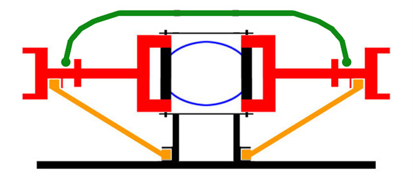
You are correct that the diff being offset added to the complication of setting pinion angle, but not if the diff and trans are both parallel to the car and thus parallel to each other. I once herd a guy say, when looking at this exact problem that "with the pinion being offset you will have problems even if the pinion and trans angles are parallel because u-joints don't like multiple angles" At the time it struck me as kind of odd because the the driveline only sees one angle which is a combination of the angles and the distance between the parallels. Make sense?? (assuming no limitation on u-joint bends) It doesn't matter where the transmission and pinion are located in relation to each other as long as they are parallel on ALL planes. For two u-joints to cancel each other out they must be opposite angles at all times and as long as the transmission and pinion are both parallel with the car, and set at parallel angles then there over all angles will be opposite and cancel each other out. This is a tall order as most Mustang dont allow the transmission to be parallel with the car. I tried for years to square mine up and was not able to do it until I got adjustable engine mounts and now it lines up perfect.
In this case my over thinking, and the part I would like your thoughts on (I do appreciate your thoughts on pinion angle) is weather the suspension should travel perfectly vertical or if there would be any problem with it having a few degrees of positive caster. Other then the wheel moving slightly back during suspension travel I don't think it will be a problem, but I am still striving for perfection
![]() Offline
Offline
I understand everything you say about the angles of the transmission and pinion. I am sure that I don't agree, yet, with all of the assumptions and this point, I would have to say assumptions as opposed to documented facts. The stock mustang transmission not parrallel with pinion, is this good or bad? The Jag pinion angle not parrallel with the transmission hang down, is this good or bad?
I wish there was something more technical that we could use to base the decision on.
Thinking about your question regarding the caster change during suspension travel ... I can't think of anything that would cause an issue. Even with a leaf spring car the rear end is designed to move a little to the rear during suspension travel because of the shackles. Certainly the forces acting on the lower control arm are fighting each other but the angle is so small that I can't imagine it being a problem.
It is interesting though ... the pinion angle set to 5 degrees does create a compromise of sorts ... LCA angle not perfect so that the u-joints can be perfectmaybe it's the lesser of two evils.
![]() Offline
Offline
Ideally you always want the center line of the crank/transmission to be at a complimentary angle to the center line of the pinion so when viewed from the side and viewed from above these lines will be parallel. With these planes of rotation parallel and a balanced drive shaft there will be no measurable vibration. Any deviation from this will generate vibration. Passenger cars are for the comparison are light and use a drive shaft that is proportionally light so the vibrations created by 1,2 or 3 degrees of misalignment will be absorbed by the mass of the rear end housing and/or the mass of the trans/engine. This does not mean the vibration does not exist it is just nullified by pounding on parts with enough mass and strong enough anchorage that the driver cannot feel it. Now when we place a semi in this same scenario. The 50 lbs added weight to the drive shafts create vibration so bad at 2or3 degrees of misalignment that ring and pinions can be destroyed and transmissions can have gears friction weld them self's to the journals they ride on. At 5 degrees or more misalignment, things come apart violently. period. If you install the Jag dif too far off the correct angle and have some vibration, try installing a aluminum drive shaft. The reduced mass will hide a world of misalignment. All the manufactures know this fact all too well so when you find a factory setup that was built out of alignment by 3 degrees or more and no double cardan joint, it is either sloppy work or they determined that the parts being pounded on were strong enough to survive to the end of the factory warranty. I took a class provided by Spicer years ago and this is what was taught. I think you can still find proof of this somewhere in their website.
![]() Offline
Offline
You are a wealth of knowledge!! Good to see you posting again as it has been a wile do you think this is also why some OEM drive shafts come in aluminum?? cheaper to run the aluminum drive shaft and then run a weaker pinion and trans? The reason I ask is I think of the Astro... why would a mini van have an aluminum drive shaft.
![]() Offline
Offline
The primary reason the OEM's started using aluminum drive shafts is to comply with federally mandated fuel mileage limits. The less weight in your drive train the less HP required to turn it. all items hat rotate at crank shaft speed have the most drag on power. overdrive transmissions rotate the drive shaft faster than crank speed making it a serious threat to gas mileage. This is why the OEM's use aluminum drive shafts. One enormous draw back is the critical speed and fatigue strength. goto go more later
Sorry about the typo's Critical speed of a drive shaft is the relation between the two factors of drive shaft design. This is only the fundamentals. The diameter of tube v.s. length. The longer the drive shaft the larger the tube must be. All drive shafts will begin to vibrate like a guitar string with high enough rpm's. If rpm's continue to climb the vibration will be followed by catastrophic failure.The test videos Spicer played had about 10 examples of critical speed failure. The high rpms combined with the harmonic vibration creates an instability in the center of the shaft that can only be described as a fragmentary explosion. The point where the harmonic vibrations begin is the critical speed. This is not due to an imbalance it is a by product of the tube drive shaft design. The longer the length, smaller the dia. the lower the critical speed. Shorter length and larger tube dia. the higher critical speed. The rpms required for critical speed are much lower than most people are aware. I have a drive shaft calculator made by spicer so I will throw out a few common sizes and diameters. These speeds are the highest speeds spicer recommends these slip yoke type shafts be run: A 3 inch dia,50 inch long shaft has a cs of 4800 rpms. A 4 inch dia,50 long has a cs of 5800 rpms I use a 3 inch dia.48 long shaft with a cs of 4800 rpms. Get this, my engine has a red line of 7500 rpms and a overdrive trans and have had it up to 184 mph. I know this seems like a red herring but steel has a much higher fatigue strength than aluminum and my drive shaft had to have been doing some wild things at 184. Aluminum would not have made it on that run. Aluminum work hardens so easy that 10 or so trips above cs would harden the tube enough to start a crack. The OEM's know this and in applications where they know they will go beyond cs and still use an aluminum shaft they will use a carbon fiber reinforcement tube bonded to the outside of the aluminum tube. This combination works better than steel in cs performance. On PU. trucks with aluminum shafts they will use a very large dia tube (6+ dia)to combat cs. This dia is impractical for any app but trucks.
![]() Offline
Offline
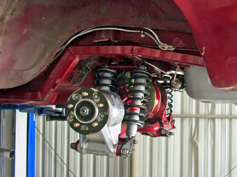
The half shafts on the Jag rear end use a double u-joint configuration identical to the drive shaft on the mustang. The pinion angle, in this case the hub, is rarely going to be parrallel with the output shafts, especially with a negative camber set on the wheels. Sure they are shorter but that doesn't mean the question regarding angles is any different ... does it?
![]() Offline
Offline
I may have a solution what about double u-joints on each end?? If the problem with a u-joint is that they travel and varying speeds as they spin and it takes two at the same angle to cancel each other out, than why can't a person put two joints at each end and be done with it?? than the pinion could be set at 0 and the transmission could be at what ever angle it happens to hang down at. It is my understanding that two u-joints at each end would give you a CV joint rather than a u-joint. I was thinking a person could get 4 of the driveline flanges that bolt to the differential and have a ring machined so that two could be bolted together. Than you could have slip yoke, u-joint, H piece, u-joint, drive line, u-joint, H piece, u-joint, flange, and then the differential. I don't know if that is a really good idea or an accident weighting to happen, I simply don't know enough about drive-shafts.
![]() Offline
Offline
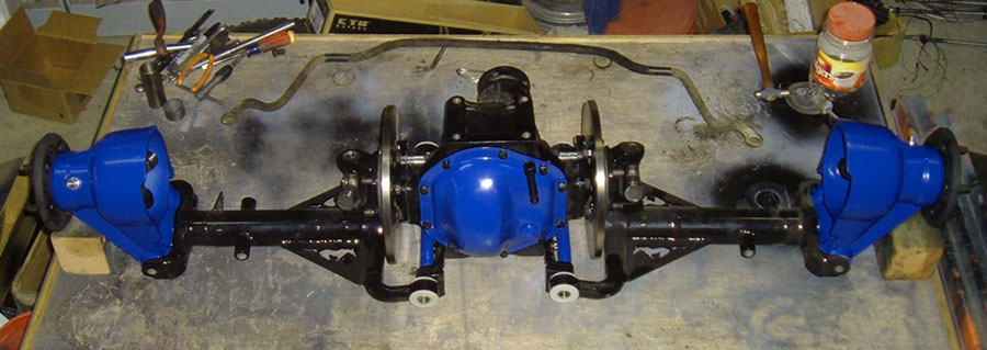
Double Cardan Funny you should mention that. I was just having a conversation with my brother and he mentioned that the when we pulled the IRS from the Jag that it had a double cardan u-joint.
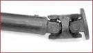
I will most likely go this route
![]() Offline
Offline
thing is, wouldn't you need two?? one at each end and if so how does that effect... the slip yoke?? as you know the OEM mustang slip yoke was designed to accommodate the differentials movement but with a Jag I believe everything was mounted solid so I wonder if the slip yoke will cause problems?? Also seams like the Jaguar driveline was attache to the underside of the car to keep it from flopping around.
![]() Offline
Offline
Don't know yet Initial reasearch, and I need to do more, indicates that one single on the front of the drive shaft and one double on the rear is the way to go. This addresses specifically issues where the angles are not quite right. We think the driveshaft on the 69 Jag that we worked on was configured this way.
![]() Offline
Offline
Take a look at this web page. I have not looked over all of it... but what I have looked over seams like good info. It is geared toward 4X4 applications, BUT most of it should apply directly to out situation. I am especially impressed that there is References at the bottom
joe, what was your doner IRS cars year and model?? I have been trying to find info on Jaguar drivelines and non of the ones I have found have been double cardan
Last edited by Daze (10/27/2011 1:53 pm)
![]() Offline
Offline
It was a 1969 XJ6
![]() Offline
Offline
Reviving this thread so it can be moved to the current topics forum.
![]() Offline
Offline
The only thing which comes to mind with the double cardan u-joint would be the addition to rotational mass. Since the transmission and rear axle are fixed, there shouldn't be any problem with binding.
Also, how would it affect the balance of the drive shaft? I'm assuming the drive shaft can be balanced with the double cardan u-joint but I have no idea.
![]() Offline
Offline
Double-cardan joints I think have rotational-speed limits, so do your calculations on what the driveshaft RPM will be at the max speed you want to be able to run.
Many cars these days use Rzeppa-type ball-and-cage CV joints in the driveshafts, BMWs typically have one at the rear for instance, the '08 GT500 shaft I've got in the shop has one BMW-type non-plunging CV at the rear and a big Porsche-axle-type plunging CV in the middle.
1 of 1