|
|
|
 |
 |
 |
You are not logged in. Would you like to login?
![]() Offline
Offline
on May 20, 2010, 12:58 pm Joe wrote:
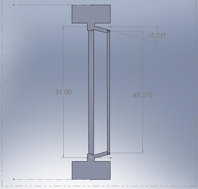
I had quite a bit of trouble determining the angle of the steering arm mostly because the spindle is on the car and my car is still a driver. My first attempt got me close. Jacked up the car and pulled the wheel off and stuck my head up under the driver's side fender. The distance from the ball joint to center hole of the steering arm was 7.0" right on the money. I then took a square and attempted to measure the offset from the ball joint to the center hole of the steering arm. The splash shield made this difficult and I had to take two approximate measures and add them together ... 2" +/- 1/4" ... not very precise. Some simple trig on the dimensions and you get 16.6 degrees
After a couple of days of not being satisfied with the degree of error I took some more measurements. From zerk fitting to zirk fitting on the lower ball joints was exactly 51.0" and from center of hole steering rod to steering rod was exactly 47.5". Because I did the front alignment myself I know there is an 1/8" of toe in so I backed that out of the 47.5" for a final number of 47.375". This makes the offset on the steering rod 1.8125" Simple trig again and the steering arm should have 15.01 degrees of offset.
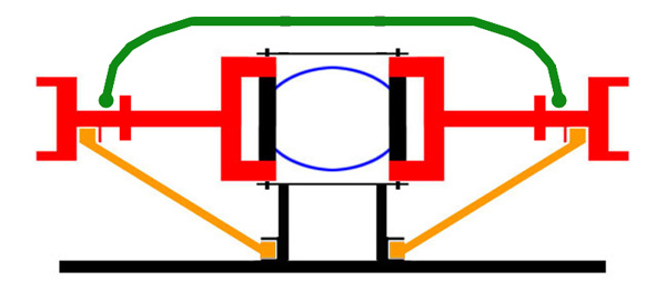
This, of course, all got started to answer a question regarding ackerman angle. So I plugged some numbers into a diagram and here's what came up.The 108" of wheelbase is a published number, 51" of side to side at the ball joints and 15 degrees of offset at the steering arm leaves almost 14" short of the 9" third member.
Curious what you guys think ... also if anyone has a 641/2 to 67 spindle laying around and wants to take some measurements
![]() Offline
Offline
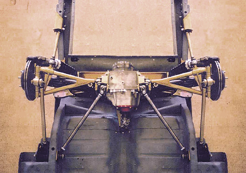
here are the same calculations for a 64.5 Mustang ball joint to ball joint 48"
tie rod to tie rod - toe 45.5"
steering arm length from tie rod hole to ball joint hole canter to center 7.25"
After doing the math the steering arm is at a 13.97º angle (probably a real world 14º) and that means thet "perfect" ackerman would make the wheel base 96.47" The 64.5 has the same 108" wheel base as the 67 so that makes my ackerman 11.53" short. That is so close to what you found on the 67 that that tells me ackerman was figured for both applications.
Further more, "more ackerman" which is what we have, results in smoother but less responsive steering. That makes sense for a 60 era production car, and I would be willing to bet most cars from this time frame had more ackerman to a similar degree of what we are finding in the 64.5 and 67 Mustang.
The problem is the MII kit is based on a 96" wheel base and so however much "more ackerman" was added by Ford will also be increased by the added wheel base. I was recently told the MII rear end was 58" hub to hub which is the same width as the 64.5 Mustang so it is a good educated guess to say the ball joint to ball joint measurements on an MII are probably similar to the same measurements on a 64.5 Mustang. With that in mind, assuming ford used a similar ratio of putting the ackerman at 89% (96.47"/108") of wheel base, the ackerman angle on a Mustang II front end would put a 64.5 Mustang 22.5" short of the middle of the differential. The good news is on the 67 you are a little wider up front so it would probably not be quite as bad, but still way more than Ford intended.
All of this is in line with the real word results, the biggest complaint I have herd on the MII kit is reduced turning radios and less responsive steering and if there is that much more ackerman, you can easily see why that would be the case.
I hope we can get some actual measurements on a Mustang II so we can figure all this out exactly instead of having to assume and guess.
thoughts??
BTW did you do the drawings on solid works again?? That is a piece of software I would sure love to have. I can't justify the $$ I guess I am stuck with cad, now if only I could get proficient at using it.
![]() Offline
Offline
I think we are closing in on some very good conclusions. I am going to use your 7.25" steering arm length because I'm sure that you had better control on the spindle when making your measurements.
I have already found an error in my calculations. I backed out 1/8" from the 47.5 which does not translate to 1/8" at the front of the tire. Since all 64.5 - 67 spindles are identical I am going to try your 14 degrees just to see what happens.
Solidworks is a lot of fun. My son is an M.E and gave me autocad about 4 months ago. It took me a day learn the software and start making parts but it does not let you move the parts through their motion. My son then gave me Solidworks and it took me a week before I could get anything to work . I can now watch the parts move and see the dynamics change. I am watching the toe-in change as the wheel turns the corner.
![]() Offline
Offline
64.5-67 are not the same Ford changed the spindles in 67 so your steering arm will be different than mine. I believe they changed spindles so they could change the ackerman to compensate for the wider track width I was positive that 66 and 67 were different, but after you said 64.5-67 were the same I wanted to double check so I looked it up in my hollander interchange manual and the spindle did change in 67.
to make matters worse my calculations are wrong too The 7.25 is accurate as I took it from an extra set of spindles, the ball joint to ball joint measurement was also correct, but the tie rod end to tie rod end measurement was not correct. I forgot that my car currently has Granada spindles on it which have the 67+ steering geometry whoops So I will take some measurements from my stand alone spindle and go again. The good news is I will have an accurate picture of the 64.5-66 ackerman once I measure up the spindle.
 1 of 1