
|
|
|
 |
 |
 |
You are not logged in. Would you like to login?

![]() Offline
Offline
No problem on the bushings Daze. the bearings are readily available. What are the bushings made out of and would this work for the inner fulcrum shaft on the LCA? Perhaps replacing those needle bearing/bushing combos ? I was playing around today, double checking what I need yet. I need to do a loose assembly to get my X member figured out. I painted stuff mostly to keep it clean and not rust until I get to the narrowing part of the job.
Do you guys think 2-1/2" square X 3/16 sidewall tubing would be adequate for a X-member ? I'm pretty sure it will be a straight section between the frame rails.
![]() Offline
Offline
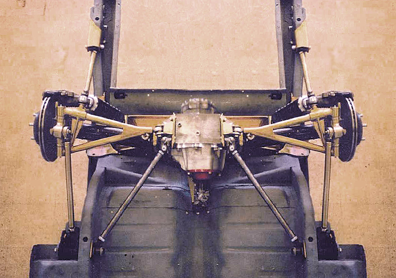
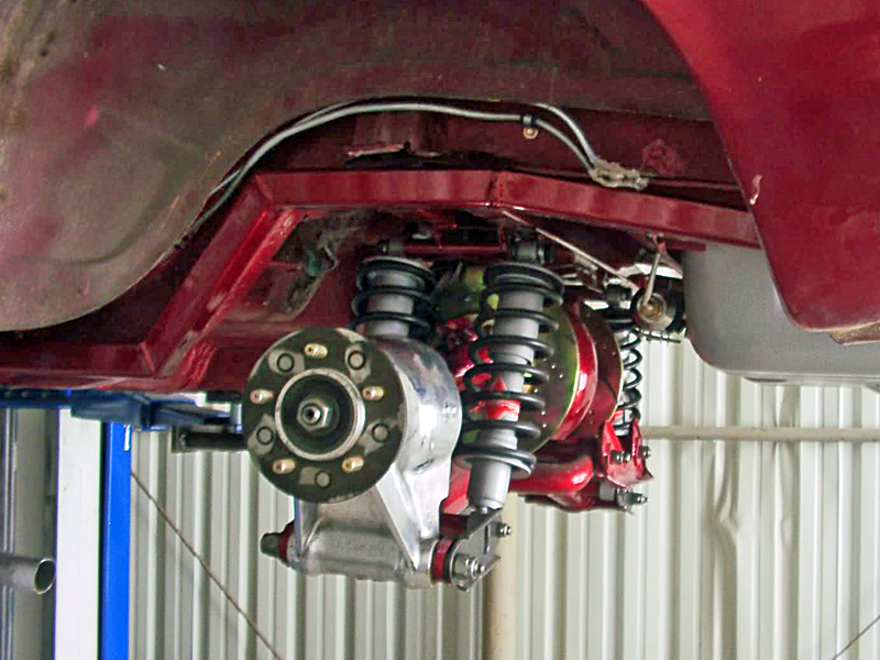
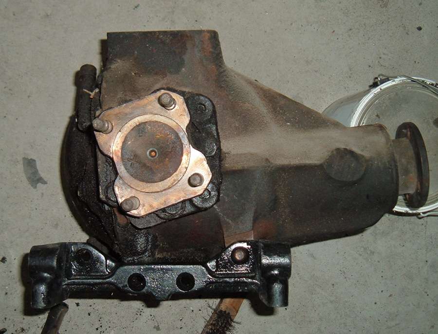
This is where it is going.
I know it's ugly now but I expect this to be a 2 year build to the pre- paint point. This is crude (I'ma crayon kinda guy in the art world) but hoping the end result will be something like this.
![]() Offline
Offline

I used the plastic bushings in the outer pivot on one car and the stock timken bearings in the other. I'd go with the timkens. More rigid, and from sitting, surface rust on the pivot shafts caused the plastic bushings to bind up. It'll have to be driven to loosen up the rear suspension.
JB
![]() Offline
Offline
Timkens are on their way. Question ?? How important is it to use those tapered bolts on the lower LCA mounts ? I was thinking of either seeing if collets would work or fill them and redrilling and countersinking.
![]() Offline
Offline
the tapered bolts are important because the correctly locate the arms. I used regular bolts and then a cone adapter on it however the place selling them is no longer in business.
![]() Offline
Offline
Another Question.. I was doing some experimental setup on the bench today with pinion angle and all that. Is there a practical limit to how much of an angle one might put the LCAs on? I can see right now it will take a little effort to get the shocks to work with it on the upper connection( X-member) fab. I would like to match the angle of the trans output as much as possible if not dead on, I'm going to be running an extremely short drive shaft . I know the real world likes them to match up real close on angles but have you guys got any thoughts on this? I know there was a post dealing with this somewhere, just can't seem to find it quick.
![]() Offline
Offline

The first issue is the transmission output shaft to pinion angle. They need to be parallel, if not a vibration can occure. When a universal joint has any angle, it induces speed variations at differnt points of rotation. When the angles are the same one universal cancels the other out. This is also why you see both ends of the driveshaft universal mounts the same.
Second, drive shaft angle as far as I have read ideally should be 3 degrees. Zero angle transfers the best use of power, but this causes the univesal needle bearings to not rotate. Giving an uneven wear, they will flat spot, causing early failure. If your OK with that, zero is fine. Some racers use zero angle.
Last edited by Ralphy (10/07/2011 7:57 am)
![]() Offline
Offline
Digz wrote:
Another Question.. I was doing some experimental setup on the bench today with pinion angle and all that. Is there a practical limit to how much of an angle one might put the LCAs on? I can see right now it will take a little effort to get the shocks to work with it on the upper connection( X-member) fab. I would like to match the angle of the trans output as much as possible if not dead on, I'm going to be running an extremely short drive shaft . I know the real world likes them to match up real close on angles but have you guys got any thoughts on this? I know there was a post dealing with this somewhere, just can't seem to find it quick.
Oh the great pinion angle debate. You can ask this question and get 12 different answers that all make sense especially in relation to IRS. here is some info I posted on the old forum and will give you something to chew on before I go on with some more info.
This is a repost from the Mustang forum I frequent to get the ball rolling here:
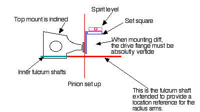
Ever go to do research on something and find your self, smack dab in the middle of a huge debate?? I recently did. I was trying to decide what I wanted to do about the pinion angle on my Jaguar IRS install. There is a 5-degree slope milled in to the top of the differential that could easily be used to set the pinion at a 5 degree up angle. (perfect since my T5 n my Mustang hangs down 5 degrees) The cage on a Jaguar IRS unit has the opposite 5 degree slope in the differential mounting section which cancels out the 5 degree slope on the differential and sets the differential up with the pinion flange perpendicular to the ground. I completely understand the importance of setting up the correct pinion angle but Jaguar had set the system up with 0 pinion angle when there transmission angle is around 3 degrees. This made me wonder what others had done, mount it with a matching pinion angle or mount it with the pinion flange perpendicular to the ground.
As I began to read up on the subject I found several long debate threads on several forums. the debate was as heated as the one we in the Mustang community see between modified and original. One thing I learned is that Jaguar rear ends have been set up both ways and in both situations seam to be working just fine.
Argument for setting up a matching pinion angle on any rear end
the following info was posted by a 34 chip on the NSRA forum
first and foremost a universal joint is NOT a constant velocity joint.(this is where the concern lies). this means if its driving a shaft at any angle other than zero, although the half of the joint that is connected to the transmission is rotating at a constant velocity the other half of that same joint is NOT rotating at a constant velocity it is actually constantly accelerating and decelerating on each revolution as the joint is working itself around the angles .at one point it has further to travel because of the angle and so speeds up and at another point it has less distance to travel and so slows down(relative to the trans speed).this means the prop shaft is rotating in a 'jerky 'movement constantly slowing down and speeding up even though the trans is at constant speed .now down at the diff end this 'jerky ' rotation will be transferred to the diff u joint which will be transferred to the wheels so what we would have is the trans trying to drive the wheels at a smooth constant speed but the u joint is trying to slow down and speed up the wheels. this means they are in conflict together causing stress and vibration. the more the angle the worse this 'jerky movement becomes. now to get over this if the diff pinion is set parallel with the trans the half of the u joint at the diff end connected to the diff pinion is also rotating with this 'jerky' movement, slowing down and speeding up each revolution but its equal and opposite to the trans u joint so they cancel each other out and the result is the diff pinion and trans are rotating together at constant speed however the prop shaft is still slowing down and speeding up. twice per rev in fact .if the diff pinion is not set parallel with the trans then this canceling effect does not take place and so the diff will not be rotating at a constant speed in relation to the trans. it is for this reason front wheel drive cars use constant velocity (CV)joints on their driveshafts not u-joints because if you imagine a front wheel on full steering lock the angle of the wheel compared to the drive shaft would be so great this slowing down and speeding up of the wheel joint would be so severe while the drive shaft is trying to go at a constant speed it would shake the whole thing apart instantly. saying all this because the angles we're dealing with are relatively small compared to the front wheel drive scenario if the diff pinion isn’t parallel with the trans then maybe its not noticeable from a driving point of view but this jerky movement is still going on and can cause premature wearing of the joints but as many rods aren’t driven as much as a daily probably not noticeable.
This info is WHY we need to set up the correct pinion angle in any car, but when you point this out to half the individuals who have put an IRS in their car , truck, or hot rod you get one or all of the following replies, with the first one being the most common:
"It doesn't apply because the Jaguar differential is hard mounted where as a live axle differential moves up and down with suspension travel"
"Jaguar didn't do it that way"
"The lower control arms (wishbones) on a Jaguar IRS are perpendicular to the pinion flange so mounting the diff at 0 degrees pinion angle allows the suspension to move perpendicular to the road. If you set the pinion at an angle the wishbones will also be at an angle and move backwards as the suspension compresses."
In my opinion the first response is nothing more than something that "sounds good" to try and justify doing it, but really has no bearing on the issue. As the pinion on a live axle moves up and down the angle (in theory) is not changing and the pinion is remaining parallel to the transmission, further more if the road is smooth and the live axle springs are stiff enough the amount of differential movement will be minimal, but you still want the correct pinion angle to prolong u-joint life.
The second response, I believe, is the main reason this debate has two divided camps. “Jaguar did it that way so it must be right." To a point I tend to agree with this sort of thinking. Having no formal training in engineering I must trust the designs of those that do, however this argument is in my opinion only completely valid IF AND ONLY IF you set the system up completely as Jaguar designed it, with a cage, with Jaguar cage mounts that have a specific amount of flex designed in to them, with Jaguar trailing arms, and with the transmission angle at 3 degrees down. The more of these thins you change, the argument “that’s the way Jaguar did it" becomes less and less valid as you are not setting it up the Jaguar did. Coupled in with this, as hot rodders copied the way Jaguar did it, and then helped others do the same thing they said “this is how I did it and it works just fine"
The third argument seams to me to have the most validity, and I speculate is the reason that Jaguar did things the way they did. If the pinion is perpendicular to the ground the wheels will stay centered in the wheel well, and all forces will be applied vertically. All that said I do not see , with only being 5 degrees off of perpendicular, that there would be that big of an issue. I did a little math and with a 5-degree angle on the wishbones 3" of suspension travel would only result in .262" of backward movement at the wheel. A leaf spring set up moves the wheel backwards at least that much as the spring compresses so I fail to see the issue.
This is probably our most talked about topic on the forum and the reality is there is truth to both ways of thinking. In the case of the "suspension angle first" I have herd of people running there suspension at 0º and the pinion at an angle that is 3º to 5º different than what would be parallel the transmission and have had no problems, no u-joint failure or vibration. As was said above Even Jag set their XJ6/12 cars up with a 3º difference between a parallel pinion and a parallel transmission so there must be some truth to it.
On the other hand those from the "pinion angle first" camp also have great success, there u-joints obviously last and don't vibrate, also there suspension seams to handle well even though there is an angle to the suspension travel.
Sense both systems seam to work I am of the opinion that compromise is the best way to go. the good news is Jag made 3 different side brackets that position the pinion at 0º 3º and 6º while keeping the suspension at 0º so the first thing you need to determine is your transmissions down angle, and you can begin compromising from there. some times the trans angle can be changed to help minimize the compromise.
in my case the trans hangs down 5º so I got the 6º brackets, and set it up with a 1º difference between the parallel plane of my transmission and my pinion. this way my suspension is still set at 0º and my pinion to trans angles are close enough
Second, drive shaft angle as far as I have read ideally should be 3 degrees. Zero angle transfers the best use of power, but this causes the universal needle bearings to not rotate. Giving an uneven wear, they will flat spot, causing early failure.
I have researched that a lot and my understanding is different. the 3º you speak of is not the drive shaft angle, but rather the angle of the drive shaft in relation to the parallel plane set up between the pinion and trans angle. these are two very different things as a drive shaft does not care what angle it is in relation to a level plane also I have always herd of it a a range, between 1º and 3º the other thing to keep in mind is that u-joints can absorb several degrees of mismatch between the pinion and transmission even as much as 5º with no major issues.(depending on the situation. When you get past 3º the specifics of the set up will determine weather it can be pushed to 5º or not, and obviously the bigger the difference the more likely an issue) Also a slight mismatch between the pinion and trans eliminates a need to worry about the angle of the drive line in relation to the parallel plane because the mismatch will cause the needle bearing to spin. That is why I was thrilled with my configuration. the 1º of difference is easily absorbed by the u-joint and still will spin my bearings.
![]() Offline
Offline
I know Day well enough, I knew this was going to light him up. Digz my drive shaft is at less than 3 degrees, maybe 1 degree. 13,000 miles, universals are fine. Get a socket, extension and universal. Spin it between your fingers, increase the angle and decrease it. You will see how the angle changes the direction of forces and speed at different rotation points. LOL!
![]() Offline
Offline
First off this is NOT exactly what I am trying to do , I just had the time to play with it. From talking with another van guy who has a similar setup only using a regular RA with a psuedo 4 link to keep it from spring wrapping, I am probably going to need at least an 8" drive shaft to make it servicable.![]()
Ralphy and Daze your info is invaluble to me. Correct me if I am wrong on any points please. First I can see the need for a few degrees difference on the driveshaft I can get this by staying parrallel and having a slight difference in my vertical line ?
Second, from what I'm understanding on Dazes comments I can adjust the LCA mounts to O degreesby tilting them ? Ithink I could add to the existing bracket and rotate it down. Or perhaps make up an adapter bracket from the RA to the LCA mounts to get the angle then allowing the thickness of that bracket when I shorten the LCA ?
My concern on keeping the LCA mount at an angle is the issue it raises with the Coilover shock mounts on the New X-member above. On my current Van I have the pinion and trans set parralel but had to run a 7 degree angle on the driveshaft with no problems so far ( 2 season of recreactional driving and tire squealing) . I know I'm moving slow on this but things have to happen to allow me time to work on it. And I just like having a good idea of what I may run into as I go a little ahead of time.
![]() Offline
Offline
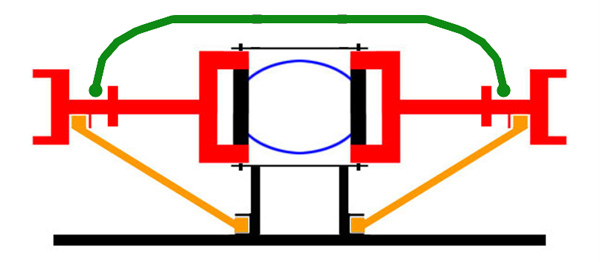
It's not complicated at all, pictures explain a lot.
Last edited by Daze (10/08/2011 8:36 am)
![]() Offline
Offline
to git different pinion angles you need to replace the side brackets. the XJ6 put the pinion at 0º and XKE brackets put it 6º there is another model of Jag that has a 3º bracket but I can't think of what it is at the moment. before you can figure out pinion angle you really need to hang the trans and se what range you have to work with.
![]() Offline
Offline
Okay.. I want to keep the pinion angle parallel with the trans. I came up with this...
I finally have my mill operational so I can move on with some of this stuff. This is going to throw the vertical line of the halfshaft and LCA off a little, I havent degreed anything yet. After reading alot of the more recent posts, right now I'm wondering if I can engineer some anti=squat in by the location of new mounting hole I must make? I'm thinking 1 to 1-1/2degrees?
![]() Offline
Offline
There is one potential issue I see with that approach. By leaving the back hole and not moving it the LCE is no longer centered on the differential. Take a look at this, it is a post I made on the old forum and have not yet gotten moved to this one.
Here it is!!! my much awaited solution to the pinion angle vs. suspension angle issue
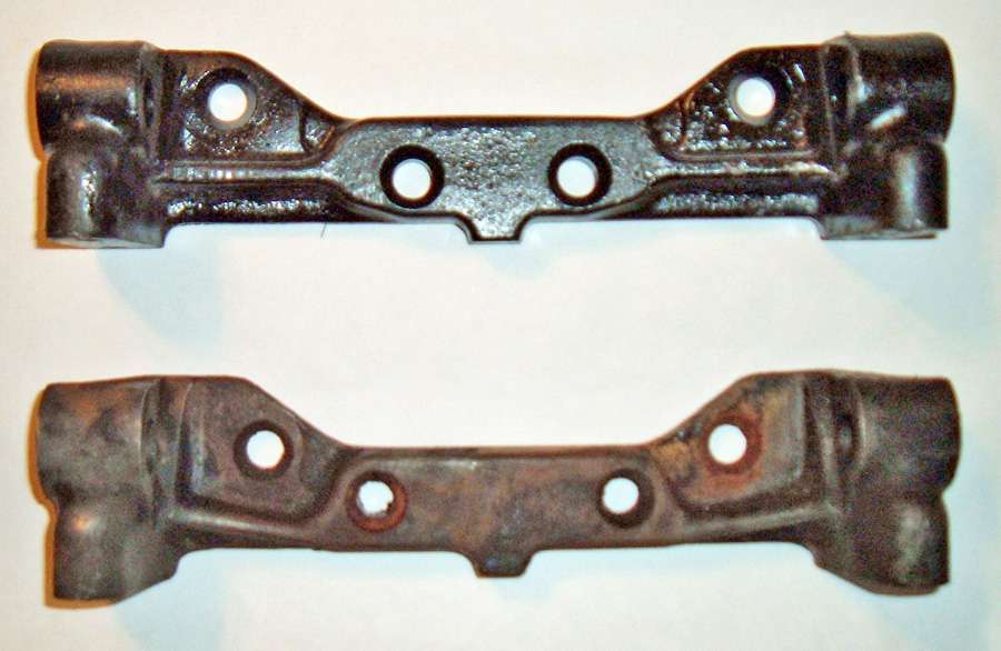
As promised here are some pictures of the parts I recently got that will allow me to maintain the correct pinion angle to match my transmission and also allow my suspension to travel vertically. The solution comes from three little letters XKE. I was going back through my loose leaf binder with the hundreds of pages of info I have gathered on independent rear suspension and one of the sections is several pages that came from CWI detailing all the differences between the various Jaguar IRS parts. One difference over the years has been the differential side brackets. They came in three different configurations: the XJ units were drilled to be parallel to the pinion, the 3.8S or saloon brackets were 3º down in relation to the pinion and the XKE brackets were 6º down in relation to the pinion which makes them parallel to the top mounting surface. By running XKE brackets I will be able to mount the diff 6º up and still have vertical suspension travel.
Here is a comparison between the two brackets. the top bracket is the XKE bracket and the bottom one came off of an XJ6.
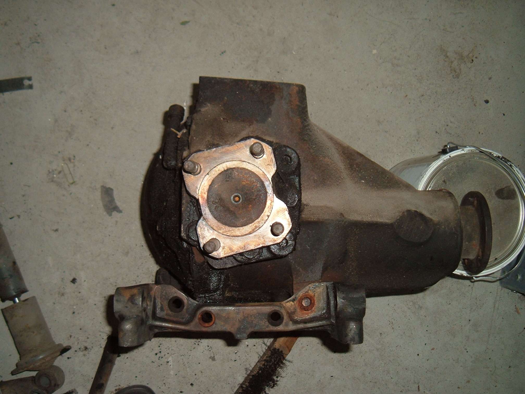
In this picture I have the XJ6 bracket on the diff and you can see how it is parallel with the pinion.
In this picture I have the XKE bracket on the diff and you can see how it is parallel with the top mounting bracket.
I have found several sources for these brackets, but In finding them I discovered that the jaguar community over the years has used them some what interchangeable and some suppliers didn't even know there was a difference. The easiest way to communicate the difference was to have the seller measure the distance between the center holes center to center. The Xj6 bracket is about 2 & 7/7" where as the XKE bracket is about 2" I can only assume that the 3.8S bracket would have holes that are half way in between these two measurements since the angle is half way in between.
Last edited by Daze (10/29/2011 8:53 am)
![]() Offline
Offline
Yes that was the issue I was wondering about. I will do a real world measurement before I totally do this , but think I also will go ahead with it for now seeing as my only other options are to find XKE brackets. I don't know if adding a degree or so of misalignment would be that critical at this stage and will be correctable by the right brackets when I can get them. The setup would remain the same. I have to keep in mind also this rig is not a daily driver and isnt going to see alot of miles on it. hmmm maybe I can jig something up to weld in and relocate both holes accurately.
![]() Offline
Offline
I did the measuring thing yesturday and WOW, there was alot more difference in the bolt location than I thought there would be. I would need to move the rear hole forward app: 3/8" to make up the 6 degree swing and keep the bracket on center with the stub axle. I will definately be on the search for the XKE brackets for the final install. I know I can make or refab these to work ,but I can not believe it would be worth the effort if I can get brackets. Thanks for the pics !
![]() Offline
Offline
my pleasure. I know CWI was welding up the holes and then redrilling them. of you look at the back of the bracket you can see the section is machined to accommodate several hole locations, so it is an option.
![]() Offline
Offline
I plugged and redrilled the holes and Yeah, it all fits in the existing bracket, Wish I had seen the Pics first ! LOL anyway one side looks good ! 
Anyway this will let me move on some.
![]() Offline
Offline
This is where I am at at this point. I have a bunch of fab work to do on engine and trans Xmembers before I can lock down the exact RA setting. Right now I am planning on tieing the trailing arms to the trans Xmember. Is there anything I should take into consideration that I may not be seeing? I am thinking straight line performance is my goal here going by the other posts on " How much is to much" . Toss in a sway bar and call it good? 
![]() Offline
Offline
what is your trailing arm plan? angled strait? how will they pivot? Are you going to solidly mount it or use rubber bushings???
![]() Offline
Offline
Right now Im leaning towards solidly mounting the RA to the frame Xmember. The trailing arms at first thought was to aim them towards the tailshaft area of the trans X using Hiem joints. Looking at it again some I may be able to go right to the frame rails running nearly straight. Again using Hiems. I may have to wait and see how it plays out to pin that down. I've got it in my mind that using the solid joints would or should require some give somewhere else in the system? I could rubber bush the Xmember to van frame mounts if needed and that would also make the entire assembly pretty easy to drop out or install.
![]() Offline
Offline
I've got it in my mind that using the solid joints would or should require some give somewhere else in the system?
The trailing arms on the Jag unit went forward right to the frame but it was not an issue because of the large rubber bushings on the front of the arm AND because the cage was allowed to twist for and aft slightly because of the mounting bushings. If you go forward right to the frame with the arms and solid mount the differential, than I would not use heim joints, or it will bind up.
That is why I ran my arms at an angle and put them in line with the inner wishbone pivots. If you do that it adds the proper support to the system but does not bind because the wishbones and trailing arms are moving in the exact same arch.
![]() Offline
Offline
A question for those who might know. How much space should I plan on leaving for aWatts link install ? This is a bit of forward thinking on my part as I am not anywhere near that point. I have been in the process of getting the engine put together and have had little time for the RA lately. But hopefully I will be taking it up again soon. I have not set any track widths in stone yet so I am completely adjustable still.
Even a rough estimate would be welcome.
Thanks Joe
![]() Offline
Offline
nicks watts set up is 4" wide. He and discussed this in detail as I have far less room between my tires and my frame rail. he came up with some solutions that could get it down to 3" but if you could have more than 4" of space you would be good to go with a stock set up.
![]() Offline
Offline
Thanks Daze. Yeah 4" is alot of realestate in that area.
![]() Offline
Offline
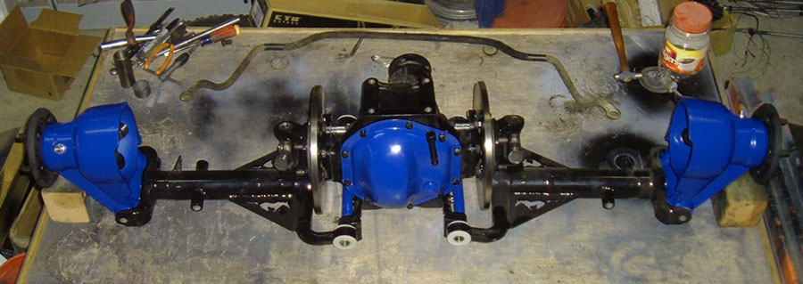
Got some time in on it today. Up on the bench and getting things positioned.
Got the bushing inserts tacked in.
Side brackets ready to tack in also.
Next is the pedestal from the X down to the Pig. Kind of up in the air here, Simple drop tube or my bro thinks I should do a dual plate that wraps the X to look better. Any thoughts on that?
![]() Offline
Offline

This is the part where I go for it knowing I did the best I could to keep things square with itself.
Went with the pedestal just for the ease of it. 
Got some welding to do and then back to Day's thread to freshen up on shortening LCAs and Halfshafts. Going to pull 2" out of each side.
![]() Offline
Offline
So. Daze do you know the reason for the amount of required bearing free play in the stock hub carrier to stub axle?
Is it to compensate for the Aluminum hub carriers thermal expansion when hot?
It is my belief that Aluminum when heated expands at such a rate that without clearance the warm bearings would expand the aluminum ,over load the bearing which would create more heat, more expansion and failure.
All tapered bearings I have come across required a pre-load on the bearing set. From transmissions to differential carriers they all require it. This is not massive preload, but always no free play. The Jag hub carrier is the only wheel bearing I have ever heard of requiring this free play preset. Modern front wheel cars all come with a type of opposing twin tapered roller bearing combined in a single outer race. These require the center nut to be torqued to a very high value to stretch the CV 's splined and threaded shaft and squeeze the two inner races until they touch. This is how the bearings get the exact amount of preload required by the bearing manufacturer..
The reason I ask is I have had steel hub carriers with the Jag wheel bearings and related parts on my car for about a year. I set the bearing,s with no free play and a small amount of preload. I have had them apart to inspect them twice since and found no discoloring from overheating or any other signs of failure. I turned my stub axle's thread transitions back in may of 2011 when I found a thread about the stress riser issue.
One more thing...
I did not use loc tite on my axle's. I agree with that idea 100% You did not say what color Loctite. Red? Green?
![]() Offline
Offline
"You did not say what color Loctite. Red? Green?" Inquiring minds want to know. LOL I'm almost at this point on mine. I have the hubs assembled but haven't dialed in the float yet. Currently working on shortening the half shafts and LCAs. Hung the pig just to get it off the shop floor for now. So far that idea is working , I put it ona floor jack and ran it up and stuck my 4 bolts in that hold the assembly to the existing frame .
![]() Offline
Offline
I like the novel approach to the "pumpkin"mount. Well done! Looking forward to more pics!
Cheers - Jim
