
|
|
|
 |
 |
 |
You are not logged in. Would you like to login?
![]() Offline
Offline
Thank you for helping me register. I am undertaking putting a jag IRS in a 1965 Chevy van. I am going to start off by saying this is my first experience with this type of set up and hopefully you guys can help see me thru it. I believe I have from the research Ive done a RA from a XJ12, typicall 4 shock set up with a 2.88 ratio. I plan on building a X member and Narrowing it some. Right now I have it mostly disassembled and will be putting new seals in the center section. The bearings seem okay, but is there anything I should be looking for that would be different from a regular set up ? Any input at this point would be welcomed. Thanks . Joe
![]() Offline
Offline
welcome to the forum!!! So do you know what year the Jag IRS is?? What do you need the track width to be to fit in the van?? Are you going to stick to the 2.88:1 ratio?? I would love to see some pix of what you are working on.
![]() Offline
Offline
Daze, Thanks for the welcome.
I'm not sure on the year, I am only guessing it in by the info you have made available. What numbers should I look for to pin-point the year? I have not determined the exact track width yet, As amatter of fact I had just started thinking about that today as I was staring at it! I think I can live with the 2.88 okay, I will be powering this with a BB Chevy , 468 with a kick.  This is one I have already done. V8 conversion, 4 wheel disc brakes, 700R4, 4.11 posi . The one I am currently working on is a 66, same body style but is a blank slate. The original driveshaft in these is only 24" long, it is a 90" wheel base. The modifications I want to make will require I move the engine rear ward and the drive shaft would be very short, that's why I want to go with the IRS. I have seen Corvette setups and I dont really like the look. I think the Jag would make a much cleaner and easier set up. I will make a new Photobucket album to get some pics of this build.
Digz
Last edited by Digz (8/23/2011 4:13 pm)
![]() Offline
Offline
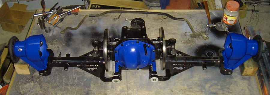
This is what I have.
Its in pieces now.
![]() Offline
Offline
looks like a fun project!!! On the XJ series rear ends there is really only one main differences and it is in the actual differential unit. The drive axles are set up differently if you have a first gen unit it uses a ball bearing axle and if you have a later unit it uses a tapered roller bearing. I look forward to hearing more about your project.
![]() Offline
Offline
Daze, from the info I got off your build pages I have a series 3 80-87, Its a 2.88 ratio with PL, Today I spent some time on the phone to find I have almost zilch for parts support here locally, Mid Michigan, I tried the links and phone # for CWI to no avail, is there a new # for them or have they changed to something else? I will be needing one of those Uhmw kits and all seals, the bearings so far seem okay except for the LCA to hub and I mucked that shaft up getting it apart on the DS . Major sieze up on those small bearings. Any info on some of these parts would be greatly appreciated. I can probably build that shaft, it seems to be a common size. Thanks Digz
![]() Offline
Offline

CWI went belly up!
![]() Offline
Offline
Thanks for the info,, I was afraid of that ! So much for easy ,,LOL
![]() Offline
Offline
The seals are available at rock auto, eBay and most auto parts places. As to the UHMW bushings I am going to offer the them if my local machine shop ever gets them done. If you need them sooner rather than later koogle components carries them I believe.
![]() Offline
Offline
Thanks, I can't wait to get that far ,,lol. I've been picking away at it during some slack times at the shop. Still in the disassembly and cleaning stages and learning as I go. I think I have the seals needed to get the carrier back together. So far thru NAPA, they are used to me doing stuff like this and are quite tolerant of returns and such. The carrier is a 4HA. I am beginning to think this RA has been somewhat assembled from parts and some of it not very well. I have run into a mislocated crush sleeve in one of the axle stubs ( it has the tapered roller bearings). cobbled up and non fitting axle seals and the hub castings are not a matched set . I have one that has some cracks in it, I'm not sure if it is totally stress related or possibly bad casting, the location has me wondering.
I had one casuallty during disassembly with one of the hub fulcrum shafts being seized up in the bearings. will need to replace or make one. I mucked up the threaded ends badly.
Today I was wondering if I should just get another RA and keep this for parts or keep going. I have no problem doing either, and seem of the luck that anything I find will need to be rebuilt anyway. LOL I'm attempting this because it is fun and Different for these rigs so anyway I go is okay.. Any Opinions on this ??
Digz
![]() Offline
Offline
Hubs like that have had a lot of discussion on the Jaguar forums. A lot of people thought they were stress cracks but the final consensus was that they were casting imperfections. Places that do rebuilds will not take them as cores. Some people have had the cracks cut out and welded up which I think is a good solution but, your best option is to replace it. I personally would not want to risk it. I know of one post on a Jag forum where a hub failed and caused a bunch of damage to the car.
![]() Offline
Offline
You probably could get it FPI inspected for little. If you were in ATL I could get it done for you. I think you can blend the area before they do so. Best to call and ask. However do not bead blast the part until inspected if you wish, bead blast will hide the crack..
It's best to smooth out any imperfections anyhow. It will make the part less susceptible to future cracks.
Last edited by Ralphy (9/03/2011 4:27 pm)
![]() Offline
Offline
Thanks again for the info and input, That FPI is a new thing to me , I will look into it more. I'm going to throw this out, The area of the defect is where the casting thins down from the shaft area, Im rough guessing 1/4". I'm kicking around grinding it out TIG'n it back and adding another web up to the bearing housing. It looks like there is plenty of room for that? At least I'm not seeing as how it could cause any obstructions.
Daze, If I was to replace the hub , where is the best place to get parts like that?
![]() Offline
Offline
To me it looks suspiciously like a cast imperfection. The area all the way to the left and the right, I'm not sure. FPI is done on non magnetic materials with a fluid, black light and a magnifier. Here is a do it yourself manufacture. The dye thins on non cracked areas and will congregate in a crack and glow do to the higher volume of die. At sometime in your life you may have seen a part that was cleaned in maybe a degreaser. Going back hours you could see a wet line that never dried, A CRACK! The die works the same way.
Get some mineral spirits and clean the area(wet it well), drip dry and let it set. Once the part starts to dry look at the area well (magnifier) both sides. It may (a crack) show up.
Last edited by Ralphy (9/04/2011 6:52 am)
![]() Offline
Offline

I think those are typically stress cracks from shrinkage in the original casting process. Not usually recognized as a cause for failure but for a high horsepower application probably not what you want to see. While drilling the ends of the crack might stop crack propagation (as in a stitch repair) I'd want either a sound part or a welded repair. You were talking about getting a second rear assembly for parts. That should solve your problem.
JB
![]() Offline
Offline
Digz wrote:
I'm kicking around grinding it out TIG'n it back and adding another web up to the bearing housing. It looks like there is plenty of room for that? At least I'm not seeing as how it could cause any obstructions.
Daze, If I was to replace the hub , where is the best place to get parts like that?
Like I said this is a mildly common issue in the Jag community. In most cases cracks like that go all the way through. If you want to do a repair removing the material and tiging it is a possible solution. I do not think you need an extra piece of webbing. Like Jim said removing a crack is not as simple as just grinding it out. You need to drill out the ends of the crack or the repair will not hold and a new crack will form. A replacement unit could probably be gotten for far less effort. David at everydayXJ can probably hook you up with a new hub for a good price.
![]() Offline
Offline
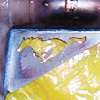
Searching the net I see this is an issue and that is exactly where they crack. I guess this should serve as a heads up for all Jag people.
REAR HUB CARRIER CRACKING: Joe Bunik reports that the cast aluminum hub carriers on his car cracked in the area just above and outward of the fulcrum shaft. The crack was parallel to the fulcrum shaft, but just far enough above it to be in the structural portion between the fulcrum shaft bearings and the wheel bearings. According to his mechanic, this is not an unusual problem.
Folks, if this part breaks at speed, you will be taking the Lord's name in vain! These parts are expensive, but if a crack is found it would be foolish indeed not to address it.
What with the rough surface on the cast aluminum combined with the dirt and grime normally covering it, it is entirely too easy not to notice a crack like this. Whenever a rear wheel is removed, it is recommended that the hub carrier be cleaned up a little and inspected for cracks, especially in the area just above the fulcrum shaft.
Last edited by Ralphy (9/05/2011 6:42 am)
![]() Offline
Offline
Also note the warning about the threaded end of the stub shaft:
"REAR AXLE FAILURE: Jan Wikström reports on his problem and solution: "The stub axle in the hub carrier (the bit that turns in the rear wheel bearings) is splined for the hub and has a large thread and castellated nut on its outer end. This thread comes right down to the splined part with no fillet whatever and creates a horrendous stress concentration at the end of the thread. Mine suffered a fatigue fracture in consequence; my local parts pusher tells me this is not uncommon, as one would expect from such an elementary error, especially if the nut is overtightened. Accordingly, I ground and polished a shallow rounded groove at the base of the thread of the new part... (see Figure 10 and Figure 11, illustrations graciously provided by Wikström).
"The next time you do the rear wheel bearings or U-joints, I strongly recommend having the stub axles checked and modified; any competent engineering shop will know about stress relief. Modifying parts of the Jaguar may be sacrilege to some of us, but fine as the design is, it isn't perfect..."
If the stub axle has already broken, it is possible to fix it by drilling and tapping a hole in the end and using a bolt and washer instead of the nut. GT Jaguar offers a grade 8 bolt and a specially designed washer for this purpose, although you could conceivably come up with suitable parts from local sources. This fix may also be used as a preventative measure, since cutting off the stub and drilling for the bolt eliminates the stress concentration in the original part as well as the shallow groove does.
Perhaps one thing to note is that GTJ offers these parts at all; that would seem a serious indicator of just how common this problem is, and how important it is to address it."
JB
![]() Offline
Offline
I used to cut a lot of threads. We always undercut the end, we used a 1/32 radius triangulated insert and cut to the same depth as the root diameter of the thread plus an extra .005.
Last edited by Ralphy (9/05/2011 10:57 am)
![]() Offline
Offline
Also note the warning about the threaded end of the stub shaft:
"REAR AXLE FAILURE: Jan Wikström reports on his problem and solution: "The stub axle in the hub carrier (the bit that turns in the rear wheel bearings) is splined for the hub and has a large thread and castellated nut on its outer end. This thread comes right down to the splined part with no fillet whatever and creates a horrendous stress concentration at the end of the thread. Mine suffered a fatigue fracture in consequence; my local parts pusher tells me this is not uncommon, as one would expect from such an elementary error, especially if the nut is overtightened. Accordingly, I ground and polished a shallow rounded groove at the base of the thread of the new part... (see Figure 10 and Figure 11, illustrations graciously provided by Wikström).
"The next time you do the rear wheel bearings or U-joints, I strongly recommend having the stub axles checked and modified; any competent engineering shop will know about stress relief. Modifying parts of the Jaguar may be sacrilege to some of us, but fine as the design is, it isn't perfect..."
If the stub axle has already broken, it is possible to fix it by drilling and tapping a hole in the end and using a bolt and washer instead of the nut. GT Jaguar offers a grade 8 bolt and a specially designed washer for this purpose, although you could conceivably come up with suitable parts from local sources. This fix may also be used as a preventative measure, since cutting off the stub and drilling for the bolt eliminates the stress concentration in the original part as well as the shallow groove does.
Perhaps one thing to note is that GTJ offers these parts at all; that would seem a serious indicator of just how common this problem is, and how important it is to address it." JB
I did some serious research on this matter, and cover it in great detail on my web page. I talked to a lot of Jag owners and looked at a lot of stories about this and the main cause of this issue is not using any or not using enough lock tight on the stub axle. After doing all my research this is the info I came up with and posted on the Jag lovers forum and the info was met with agreement. from there it became part of my web page and the following is an excerpt from my web page.
" - I am about to cover one of the most important steps of rebuilding the hub, which involves correctly shimming the stub axles, but before I do, I want to address a potential issue that I learned about that deals with the possible failure of the stub axles. I found this information on Jag Lovers Forum and it turns out that, in more than one case, the nose of some stub axles have sheared off, allowing the stub axle to separate from the hub. Since the half shaft and stub axle serve as the UCA, if the stub axle were to separate from the hub, the hub would no longer be held in two places and the wheel will probably no longer stay perpendicular to the road. If this were to happen while driving the car, the results could be catastrophic. Alarmed by this possibility, I began to extensively research this issue and learned several things.
Summation of problem factors and causes:
1. The sharp cut of the threads creates a natural stress point.
2. The sudden increase in diameter from threaded to splined section increases shear forces at the base of the threads.
3. Failure to correctly assemble the hub WILL increase the chance of sheering of the threaded end.
4. Unknown past damage to the hub parts, such as that caused by an accident, will also increase the chance of sheering of the threaded end.
5. Older parts are made of mildly lesser materials so, in theory, a stub axle from a newer IRS unit should be stronger than that of parts from an older IRS unit.
6. Lack of routine maintenance significantly increases risk.
Solutions:
1. To insure that you have a quality used stub axle, have the base of the treads magnofluxed to detect existing micro cracks, or at least use a crack testing solution. It cost me $20.00 to have a local machine shop test my stub axles. This is cheap insurance to insure the parts I am using will function for thousands of miles to come.
2. ASSEMBLE THE UNITS CORRECTLY!! My research found this to be the most important factor in dealing with this issue.
I. Use locktite !!
II. Measure and shim the stub axle for correct end-float
III. Torque down castle nut to factory specs
IV. Make sure the stub axle does not bottom out on the washer and castle nut
3. Routine maintenance, I was amazed when I first looked at the maintenance schedule of the Jaguar IRS unit and how much needs to be checked on a mildly regular basis (every 6000 to 10,000 miles depending on the parts).
4. In relation to point 3, if the bearings in the hub are worn out and the shaft has too much end-float, the side-to-side motion will work harden the threaded base on the stub axle, causing it to crystallize and increasing the chance it will sheer off.
5. Be one with the car. Be aware of what the car is doing, how it is handling, and how it sounds. If something changes, find out why.
6. Cutting a small rounded stress reliever (by a qualified machinist) especially in relation to the sharp grooves at the base of the threads may be a viable preventive solution. I, however, chose not to do this as I knew that the stub axles I was using didn’t have any cracks and that the hubs would be set up correctly.
7. Newer parts from say a series III Jaguar, both hub and stub axle are more likely to be stronger than that of the corresponding parts from a series I Jaguar.
8. Do not abuse the suspension. If you drive hard and fast over rough roads all the time, then know the life of the parts will be reduced and routing maintenance needs to be increased.
- I believe in the concept of knowing all the facts so as to make an educated, informed decision, and with that in mind, I wanted to address the potential issue mentioned above. I also wanted to use this information to stress the importance of correctly setting up the hubs. Keep in mind that just because there is a chance this could happen, it is not likely that it will, especially if the solutions above are heeded. Lets face it, the side of the road is not littered with Jaguars that have sheared off their stub axle threads, so the actual extent of this issue is minimal under NORMAL conditions and, even though the Jaguar IRS system may have room for improvement, it has proven itself reliable when maintained properly.
"
Last edited by Daze (9/05/2011 10:56 am)
![]() Offline
Offline
So this locktite recommendation.... That is for the nut? Or is it for the spline as well?
JB
![]() Offline
Offline
So this locktite recommendation.... That is for the nut? Or is it for the spline as well?
JB
The locktite goes on the splines. There is a hole in the tip of the half shaft and the nut is a castle nut so you use a pin to lock it in place. Using the locktite on the splines is not a recommendation but rather required. It is how Jaguar did it and is in the directions in the OEM shop manual. A lot of people who rebuild their hubs don't realize this and that were problems arise. When you go to take apart most OEM assembled hubs, you will know it because with out a torch and a press the half shaft is almost impossible to get out.
![]() Offline
Offline
That explains a lot. Guess I have a couple sets to rework then. Luckily neither car has been on the road yet.
JB
![]() Offline
Offline
I took the hubs to a friend of mine that has a small foundry and makes alot of aluminum castings. he figures it it is mostly just the result of a weak casting but we will , for now anyway, try welding it up so I can move on with the set-up. still gathering up some seals and such. I'm trying to go thru my local parts stores and some vendors we use at work. I noticed in some pics I found that the cracked webbing area in the hubs may have been dealt with by changing the casting to an X pattern in that area in later models. It may even be feasable to box that entire area in. I'm still in the "kicking it around stage" there. Also I'm not getting my head around the locktite on the splines thing. I can only see this as a way to temporarily prevent a disaster to a non wrenching driver as bearing pre load looks to be set with the castle nut on mine ,, that or I'm really missing something ! My splined axle already has a radius at the thread base. newer model part maybe ? I have to admit I havent gotten a book yet. LOL More later , just tossing in an update kinda thing .
Digz
![]() Offline
Offline
I took the hubs to a friend of mine that has a small foundry and makes alot of aluminum castings. he figures it it is mostly just the result of a weak casting but we will , for now anyway, try welding it up so I can move on with the set-up.
have you looked in to getting a new one?? I bet David at everyday XJ would sell you a new hub for about the same cost as having the old one fixed
Also I'm not getting my head around the locktite on the splines thing. I can only see this as a way to temporarily prevent a disaster to a non wrenching driver as bearing pre load looks to be set with the castle nut on mine , that or I'm really missing something ! My splined axle already has a radius at the thread base. newer model part maybe ? I have to admit I havent gotten a book yet. LOL More later , just tossing in an update kinda thing .
Digz
DO NOT USE THE CASTLE NUT TO SET BEARING PRELOAD!!!!!!! The system is not like most front wheel bearings, but rather like a pinion bearing where the retaining nut us torqued down to spec. The locktite is there to further lock the stub axle in place. Preload is set by correctly shimming the stub axle. Pleas look at my web page on hub rebuilding it has lots of pictures and will walk you through the hub rebuilding process. Here is an excerpt from my page but keep in mind there is way more info on the actual page including tons of pix:
- When installing the stub axles into the hub, the tapered bearings need the correct amount of preload or, as the Jaguar shop manual refers to it, the correct “end float" . To properly set the end float a shim of the correct thickness needs to be placed between the bearing seal plate and the inside end of the wheel flange. The brass ring that came with the hub should be perfect, however, you cannot assume that it is correct and measurements must be taken to insure that everything is set up correctly. A Jaguar shop manual gives complete details on setting the end float but also suggests that you use a special tool. Not having the special tool, I set the end float using the stub axles in place of said tool.
- To set the end float, I installed the original spacer ring and the seal plate and then slid the stub axle into the hub and installed the corresponding washer and castle nut. I torqued the nut down to 85 foot pounds, but as I did it I rotated the wheel flange to insure the bearings were seating correctly and to make sure I was not over tightening them. NOTE if the shim is too thin, the bearings will be too tight and the flange will become difficult to turn. If the castle nut can be torqued to the proper specs of 85 foot pounds without increasing the drag on the wheel flange, a dial indicator can be used to measure end float.
- When I set the end float on my hubs, I used an old brake drum to bolt the hub to. This gave me a nice solid base for the hub and provided me a large steel surface where I could attach the magnetic base of my dial indicator. With the dial indicator and base attached to the hub, I adjusted it so that the indicator was centered over the u-joint. I then put a piece of steel over the end of the hub to give the dial something to gauge off of and zeroed the gauge. Pry bars were then placed between the wheel flange and hub, and used to pry the hub upward. As the hub moved, the amount of movement registered on the indicator and was noted. When doing these kinds of measurements, it is important to take many measurements and go with the most common result.
- On one hub I was getting .002" movement, which is perfect as the shop manual says set end float between .001" and .003", but on the other hub I was getting .010" of play. Too much play meant that the spacer was too thick, so I removed the hub from the stand and took it apart so that I could get to the shim. Once the shim was out, I used my digital calipers to measure the thickness in half a dozen locations on the ring. This spacer measured out at .127" to .129" , depending on where I took the measurements. I then took a piece of sand paper and laid it out on a flat piece of steel and worked the brass spacer back and forth in an even circular motion, regularly changing my finger position on the ring to insure even removal of material. I also took measurements every few minutes to insure that I did not remove too much material. After about 15 minutes of working the piece I had it down to .124" all the way around the ring and even though I had only removed .005" and probably still needed to remove an additional .003" of material, I reinstalled the part into the hub and set back up the dial indicator to take a second reading. This falls into the concept of “measure twice cut once." My first measurements indicated that I needed to remove .008" of material but I wanted to double check so that I did not accidentally remove too much material and ruin the spacer. The second round of measurement confirmed that there was still .005" of end float, so I once again took the hub apart and continued working the spacer. I removed an additional .003" of material so that both hubs would be set up with the same amount of end float. I confirmed that the end float was .002" by reassembling everything and measuring a third time.
Also here is a helpful you-tube video that will give you some good info, but read my web page first.
![]() Offline
Offline
Okay I see what you are saying on the stub shaft now ! I can do that. Just for background I have a pretty well equipped shop and have backround in heavy equipment, operation and repair and fabricating. After re-reading your set-up guide( yes I did read it before,, but apparently to quickly) lol, I see the need for the locktite. As far as cost to rework the hub housing ,that is nil and I am always looking for ways to improve a design. I did send a parts inquiry to everyday XJ and have gotten no response as of yet. Perhaps a direct email would be better ?
Daze I haven't ordered the small bearings for the outer fulcrum shaft yet, I was wondering what the status was on the bushings you talked of having made? Those look like the real deal in that spot. Thanks for all the info
Joe
![]() Offline
Offline
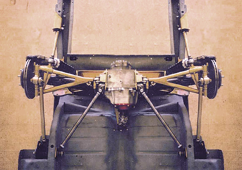
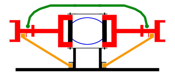
Different ideas progressed in design through the years. If you look where the Corvette C4's toe rod is located, it eliminates this twisting problem.
Last edited by Ralphy (9/26/2011 7:27 am)
![]() Offline
Offline
Thanks Ralphy, if I am understanding the terminology correctly you are referring to the link by the spring? My casting friend thru some weld on the cracks which he thinks were mostly surface casting defects and closed in the the entire area with a .200 plate.
I think this will work out for me for now. This rig isnt running a road course, ( mostly a noise maker that can run if it wants to). I went ahead and ordered the small lower outer fulcrum bearings. I want to get it reassembled enough to get my setup started , X-member and what I need to shorten. Perhaps I can figure out a way to incorporate some kind of linkage similar to that if needed. Will definately keep it in mind now.
Looking good!!!! sorry I never got back to you about those bushings, I am still weighting for the machine shop to get them done. I have been weighting since APRIL
 1
1 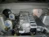