
|
|
|
 |
 |
 |
You are not logged in. Would you like to login?
| Independent Rear Suspension Forum » Differential side brackets needed » 7/16/2016 2:55 pm |
Looks like I have lucked out.
The mounts from my good rear are only drilled one so all I have to do is reverse them and I may drill any angle I like.
| Independent Rear Suspension Forum » Triumph GT6 or Spitfire & Sierra or Merkur xr4ti IRS coversion. » 7/04/2016 3:42 am |
Got better numbers and tried them in Speed-Wiz.
As I suspected it will not let me go past center for my calculations.
I can get very good numbers and avoid positive camber entirely for bump and lift, but no matter what I try I cannot seem to avoid negative camber on the out-side wheel in body roll.
Probably missing something basic, but what?
So far I've mostly kept the lower arm level and played around with upper arm length, and some variation in inner pivot point heights.
Looked at my frame and the numbers I was happiest with.
Looks like a simple set of cross-mounts and reinforcement will work.
May also be able to attach the upper diff mounts to them.
| Independent Rear Suspension Forum » Hi, I have two IRS projects to work out. » 7/03/2016 5:05 pm |
Found my answer on the arms/axle angle question!
Whatever gives me -3/4* + or - 1/4* at normal ride height.
Strait out of my old XKE manual.
Now I need a better way to measure my camber.
| Independent Rear Suspension Forum » Triumph GT6 or Spitfire & Sierra or Merkur xr4ti IRS coversion. » 7/03/2016 2:58 pm |
Mocking up the rear now that I finally have some aluminum uprights.
GT6 frame creates an issue I need to find a way around.
Original suspension used a lower arm and the top mount transverse leaf spring.
I'm using an upper and lower arm.
The main obstacle I keep running into is that the lower arm will have to be fairly short at about 8.50".
Normally the upper arm would be made a bit shorter.
That makes the upper arm VERY short in my view, particularly with the offset incorporated in the upright, so only about 4.00" for the arm.
So now wondering, can I get the camber compensation I want using upper arms that pivot from a point past frame center?
Left arm pivot point to the Right of frame center, Right on the Left.
This would be similar to what Triumph did, the leaf spring brought the pivot point to near center.
Every model suspension I look at features long A arms, nice for a scratch built frame but I do not want to have to cut away my original rear frame.
I do have a suspension modeling program but not a lot of expertise with it.
Not sure it will accept this idea to analyze.
| Independent Rear Suspension Forum » Hi, I have two IRS projects to work out. » 7/03/2016 12:54 am |
One more point to be clarified. (Yah, sure, just one more!)
Browsing the links posted into varied topics here I found a mention that a Watts lint to the top of the hub serves to eliminate wheel hop, and that a Watts link to the bottom of the hub acts as a trailing arm.
Is this correct?
Doing both might be possible but seems overly complex and likely to create a binding situation.
I really want to use a Watts link but am dismayed at the limited ground clearance I will have if I mount it to the lower arm near the hub.
Some jurisdictions will ticket you for anything that sits lower than the bottom of your wheel rim.
I find other issues with a trailing arm setup weather it is forward or rear mounted.
Getting to the point I have to decide what I am doing about this.
| Independent Rear Suspension Forum » Hi, I have two IRS projects to work out. » 7/03/2016 12:41 am |
OK, somebody answer this simple question definitively!
Every other post on the subject that I see contradicts another!
Jag IRS lower arm level at ride height, or axle level at ride height?
It cannot be both!
I can see that with the lower arm level as I have it now, the axles will be slightly inclined upward going from the diff to the hubs.
Simulate 3" of compression and the wheel camber becomes noticeably positive.
This has to be settled ASAP, I'm close to welding in the main mount brackets.
| Independent Rear Suspension Forum » Hi, I have two IRS projects to work out. » 7/02/2016 11:16 pm |
Made some actual progress!
Ideal had to yield to practical in a couple of respects.
Lowered rear ride height l.00" to only 8" to the frame bottom just ahead of the kick-up.
GOOD.
Lowers center of gravity for better handling.
Helps to get my engine to sit normally for it's designed angle.
Brings the lower trailing arms for bracing the bottom of the diff into an almost strait line.
Brought my main diff mount up on the frame rails.
BAD.
Increases the bend I need for the upper forward reaching diff mount reinforcements.
Reduced compression travel to only 3", maybe 3.5"
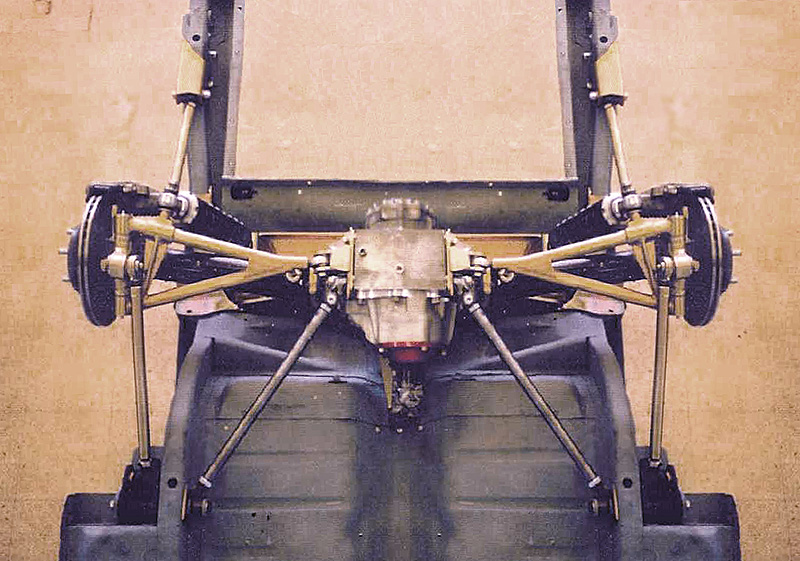
Here is an actual mock-up of my recent progress.
Main mount will be bushed at the ends.
Shock mounts and their spreaders are tacked in place.
Mounting points for the forward facing upper reinforcement are tacked in.
Lots of clearance for brake components.
Plan is adjustable shocks on the front and air shocks to lever the ride when I have a load at the back.
The round tube behind the diff is a mock-up for possible reinforcement of the rear lower diff.
30* black bars are my fixed points for shock simulation at ride height.
I have to bend tube for the forward reinforcement.
Despite my desire for light weight I seem to be overbuilding this.
I hope the added weight at least helps to balance me out front to rear.
| Independent Rear Suspension Forum » Hi, I have two IRS projects to work out. » 6/30/2016 8:24 pm |
Finally got to pick up the rest of tube I needed and some threaded ends.
Metal supply house did not have some of the tube I needed but Summit Racing carries it.
May actually begin welding this weekend.
Also get to experiment with tube bending.
May try the fill with sand first trick to avoid flattening.
| Front Suspension Discussion and Tech » Manual or Power Rack and Pinion? » 6/28/2016 12:34 am |
Welll, I lean toward as few power robbing accessories as possible.
Steering that is light around town may be twitchy at speed.
PS pump takes what, 8HP?
I may be a bit extreme about this as in addition to dumping the PS I'm also hoping to drop the PB via dual masters and a balance bar.
| Independent Rear Suspension Forum » Differential side brackets needed » 6/27/2016 4:31 pm |
Hmm, I have a sine bar and milling machine. ![]()
So this might be fairly simple for me.
I also need three degrees mounts.
Would rather buy them if the price is reasonable.
Books all say Chevy trans yoke will be Five degrees but mine is closer to three.
| Original IRS forum Content » Throw Out The Bone! » 6/27/2016 1:09 am |
Pic link is dead.
| Independent Rear Suspension Forum » Hi, I have two IRS projects to work out. » 6/26/2016 11:23 am |
Not so concerned with wheel hop as deflection under acceleration and hard braking.
I've looked at 303 Radar's pics and found my '68 frame to be very different than the '59.
I have most of my conversion figured out and will actually cut some metal today. ![]()
If I can put the Watts Link at the top of the upright I will be about set.
Looking into forming a steel extension to do that.
Looked at what the Cobra guys are using but it is too similar to the one above that extends upward several inches.
I do not need to be taller, just wider toward the inside.
I need to re-read the information on using the later F40 carriers.
Seems they may be better suited for extending inward?
Not sure of their top of the casting height vs the XJ6 version.
There was something posted about having to shim bearings, and possibly needing an adapter U-joint?
| Independent Rear Suspension Forum » Hi, I have two IRS projects to work out. » 6/26/2016 1:24 am |
Visited a local "Rat Rod" car show today, never saw so much BAD engineering in one place before.
Some of it was truly incredible, but not in a good way.
To get the images out of my head I had to work on my El Camino/JAG IRS tonight.
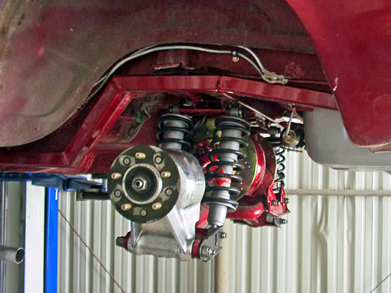
Liking the Watts Link but not happy with the lack of ground clearance if I do it the easy way, like this but I have 15" wheels.
This pic might be an inspiration. I do not have space to add to the top of my upright as he did as I only have 4.50" between the top of the upright and bottom of my frame.
Need to keep 4.00" of travel.
But if I can extend the top of the upright inward 3.00" I could put the Watts above the axles and use the old trailing arm mounts for sway bar link mounts.
So how well do the Jag upright castings weld?
Thinking I may be able to cut pieces from my spare set and weld them together to get the additional width I need.
Would also weld the pivot point support at right angles crossing the top of the weld joint for a bit of reinforcement.
Hope this is clear as I've yet to master cad for illustration.
If doable this could make a clean Watts setup.
Need to stick my spare fuel tank in the frame to verify that I have plenty of clearance for the IRS, I think I do but should verify before going further.
| Independent Rear Suspension Forum » Hi, I have two IRS projects to work out. » 6/25/2016 11:04 pm |
Beware, I have found the El Camino axle centerline and have a soapstone in hand!
Marking up metal for my mount now.
My design is probably overkill but I am triangulating the mount like crazy using original trailing arm mounts with bushings.
Rod ends sound trick but Want to isolate road noise as much as possible.
Also adding a set of low mounted trailing arm supports from the bottom of the frame to a tie bar at the front bottom of the diff.
Hoping I can put a sway-bar behind the diff.
My entire mount is a drop-out design.
Leaning heavily toward a watts link but a little concerned that the pivoting links at the lower arm will have to be pretty short to retain even minimum ground clearance.
Intuition says fore and aft links must be parallel, correct?
Fortunate that the frame is just about a perfect width.
Other than ground clearance what disadvantages might I find with the Watts?
| Independent Rear Suspension Forum » Hi, I have two IRS projects to work out. » 6/16/2016 1:43 am |
Some small progress.
El Camino frame is finally INSIDE on a nearly level floor!
Got the wheels bolted on and a stand made for the center section to keep it level.
With shims I will be able to adjust the components heights.
Bought my bushings so getting closer to fabricating the mounts.
Also bought some cast aluminum uprights for the Trick-6 rear.
Originally for a South African Lotus Seven replica, I got them from Canada.
They use my Merkur/Sierra hubs and axles.
Not beautiful but functional and I think I can clean them up using my milling machine.
Might even be able to lighten them a little.
| Independent Rear Suspension Forum » Triumph Spitfire Redo » 5/15/2016 10:33 pm |
I'm putting a custom Sierra/Merkur based IRS into my GT6.
I would never weld the half-shaft to shorten it.
Look at interchange books, you may be able to swap for one of the correct length.
If that fails you may be able to cut it shorter and respline one end.
| Independent Rear Suspension Forum » irs on a 1963 comet convertible » 5/15/2016 10:27 pm |
How similar to Falcon, which is basically the same as early Mustang?
Lots of Mustang info available.
| Independent Rear Suspension Forum » MN12 IRS in '68 Cougar » 4/17/2016 12:05 am |
As I recall the Cougar was a slightly heavier and upmarket Mustang.
Pics of where you are with this might be helpful.
| Independent Rear Suspension Forum » Looked at a Cadillac Catera IRS today. » 3/20/2016 7:05 pm |
Have no pics and not sure if they would go under Chevy or import since it's a GM car on an Opel chassis design. ![]()
Aluminum center section, semi-trailing arms, and drops out on a cradle frame so should be fairly easy to adapt.
Suspect that newer CTS is similar.
The quad-cam V6 engine is surprisingly attractive and can be mated to manual trans.
Probably a PAIN to adapt to other cars though due to excessive electronics issues.
| Independent Rear Suspension Forum » "Idiots Guide" to basic IRS related info? » 9/19/2015 10:44 am |
Poking around the web is seems ideal CV joint angles are between 3 and 15 degrees with a momentary maximum of 35.
Some angularity is necessary to circulate the grease and minimize heat.
So having the arms canted back or forward a little while also "Level" at resting height is a good thing.
| Independent Rear Suspension Forum » Triumph GT6 or Spitfire & Sierra or Merkur xr4ti IRS coversion. » 9/15/2015 12:46 am |
Not directly related to the IRS but necessary in order to be able to check driveshaft length and angle.
Finalizing fitment of the engine and trans which requires heavy frame cutting.
Not actually building a frame but with the number of modifications it almost feels like it.
In order to get a Buick V6 and T5 to sit low and back in a Triumph GT6 frame I had to cut away most of the top and half the inside vertical wall of the forward half of the "Hourglass" portion.
Pics once I clean things up a bit.
Really want the bonnet to remain stock and do not want to put thick spacers under the body, it's sports car not a 4x4.
I will also be putting a curve into the top of the front cross-member to clear the crank pulley.
Crankshaft damper sits flush with the front edge of the cross member, that may give an idea how far back I'm setting the engine.
Think I figured out how to reinforce the frame.
Going to have some rectangular section steel bent to match the chassis shape where it's been cut away.
This will need to be as close to the inside width as possible and half the depth.
That will be welded inside the original chassis, which is even thinner than I had expected despite having no rust.
This restores the frame to a shallower box section.
Then I want to add another bent box section to the inside outside edge, about a third of the original width but flush to the top of the original rails.
That gives me a doubled up box section that I think will probably be stronger than the original when welded full length.
But it still leaves the extra inside width and depth I need.
Now to find a fabricator who can do the bends.
Hope my description makes sense, I have no idea how to attach a drawing even if I had one.
Also looking into changing the front IRS to eliminate the weak lower trunion.
Anyone know if 71-73 Pinto upright is actually the same as late Cortina?
I have confirmed that they are NOT the same as 74-80.
Slightly smaller and lighter, with a 4.5" arm instead of 5.0"
| Independent Rear Suspension Forum » "Idiots Guide" to basic IRS related info? » 9/13/2015 11:04 pm |
I find myself needing very basic reference information I was SURE would be handy to find here.
Things like:
How to properly measure a CV (and other) axle for length?
How to include the CV joint in measuring axle length?
Desired minimum and maximum CV angles?
Are CV joints as finicky as U-Joints for the angles at each end not matching?
Light hollow CV driveshsfts? (trans to diff).
Basic ralationship of roll center, instand center, camber caster, etc. to handling?
Basic starting points and the direction you want them to go?
Seems most discussion here assumes the reader is already fairly expert, not all of us are.
Most of this CAN be found via searching the web but it seems to me that this site could be a little more "One stop shopping" friendly if these and other basic topics were added.
Not criticising, just a suggestion.
| Independent Rear Suspension Forum » Triumph GT6 or Spitfire & Sierra or Merkur xr4ti IRS coversion. » 9/13/2015 9:02 pm |
Had not planned to do so but put a few hours into fitting the engine and trans today.
Finally have them sitting just about as perfectly as possible.
Cannot get any lower even if I had a dry sump system, bottom of the pan is even with the bottom of the frame.
Engine is dead level with the frame, I may want to raise the front just a fraction.
Front of the crank damper is just about flush with the forward edge of the front cross-member.
If I cannot get the bonnet to fit without cutting now, it cannot be done using a Buick V6 engine..
Aghast at how much of the frame channel I've had to remove for that big fat T5 and the V6 starter.
Going to have to get very creative to restore the frame strength.
Looking like I will take a page from the old Shelby Mustang, putting a removable brace between the shock towers.Find this advisable since I've had to remove some of the original gusseting to clear the oil pump.
Also cutting clearance for the front pulley in the forward cross member.
Reversing an aluminum single sheave SBC crank pulley will give me enough room to move the steering rack back 1.00" which seems to be all that should be needed.
Doing that and shortening the rack to fix the backward Ackerman and bump steer.
No room to mount the alternator in a conventional manner so current thinking is to reverse mount it.
The water pump drive may become even more bizarre, perhaps utilizing a jack-shaft from the alternator if I cannot make an electric pump fit.
Just about ready to actually put the front engine mounts in.
Would be nice to weld parts ON after so much cutting them off.
Still not certain about the front suspension.
I recall reading that some folk have adapted European Ford spindles and arms.
Since I need a 4x10⁸ pcd anyway I will look into that as well.
Once the engine and trans are finalized I can also finalize the mounting of my rear diff.
From there rar suspension mocking up should be much more accurate.
| Independent Rear Suspension Forum » Triumph GT6 or Spitfire & Sierra or Merkur xr4ti IRS coversion. » 9/07/2015 8:31 pm |
Decided that this needs it's own thread as I intend to fully dovument the "How to do" of this conversion.
Gave up on doing what some one else had done and actually made some progress today.
Mostly cutting metal but I think I've figured out how to mount the Sierra/Merkur diff!
Good thing since it was keeping me awake.
Pics once I'm a little further along.
Basically I cut away most of the original Sierra/xr4ti diff cradle except for the mounting plates and a small section of the curved tube between them.
I plan to weld some rectangular box section steel vertically to the ends terminating at horizontal brackets that will fit the original Triumph mounts.
This is similar to how Toyota and such are usually done.
In addition I also cut away the center of the rear body mount for additional space.
I will now be able to add a horizontal bar to reinforce it while also fitting an original rear Siera/Merkur diff mount.
Hoping I can get one in Poly as the original rubber is too soft for my preference.
Once done the diff will be able to drop out the bottom easily as original.
I am off-setting it a bit in order to have equal length axle shafts.
With the diff in I will be able to work on the A arms, uprights, and shock mounts.
Since this is not a sanctioned racer there are no set rules and I am free to do whatever I like for suspension.
Anyone have an "Ideal" rear suspension geometry for a 49" track and 185/14 tires on 6" rims with 4" back space?
| Independent Rear Suspension Forum » Hi, I have two IRS projects to work out. » 9/07/2015 7:11 pm |
Gave up on doing what some one else had done and actually made some progress today.
Mostly cutting metal but I think I've figured out how to mount the Sierra/Merkur diff!
Good thing since it was keeping me awake.
Pics once I'm a little further along.
Basically I cut away most of the original Sierr/xr4ti diff cradle except for the mounting plates and a small section of the curved tube between them.
I plan to weld some rectangular box section steel virtically to the ends terminating at horizontal brackets that will fit the original Triumph mounts.
This is similar to how Toyota and such are usually done.
In addition I also cut away the center of the rear body mount.
I will now be able to add a horizontal bar to reinforce it while also fitting an original Sierra rear diff mount.
Hoping I can get one in Poly as the original rubber is too soft for my preference.
Once done the diff will be able to drop out the bottom easily as original.
I am off-setting it a bit in order to have equal length driveshafts.
With the diff in I will be able to work on the A arms, uprights, and shock mounts.
Since this is not a sancioned racer there are no set rules and I am free to do whatever I like for suspension.
Anyone have an "Ideal" rear suspension geometry for a 49" track?
| Independent Rear Suspension Forum » Software Solutions for IRS design/Layouts? » 9/07/2015 12:43 am |
Managed to model the rear IRS at least enough to get a starting point.
Need to make a basic change to correct positive outside camber gain in roll.
Started with parallel A arms.
Back to reading the book.
| Independent Rear Suspension Forum » Hi, I have two IRS projects to work out. » 9/06/2015 12:43 am |
Bought the Speed-Wiz software since it was cheap enough and does much more than just suspension.
Found that it has Jag in the suspension menu so that should help with the El Camino.
Still pretty much stuck on the Spitfire/Merkur custom setup until I can figure out my basic starting points.
I know the track, wheel/tire sizes, and some basic differential dimensions.
Beyond that it's a blank piece of paper!
I have pics of a great design but no dimensions as the guy who was doing them insisted on his doing the installation.
Not practical with him being in England, beside which it seems he dropped out of doing them.
So it looks like I have to use the pics to try to get rough dimensions and come up with my own version.
| Independent Rear Suspension Forum » Software Solutions for IRS design/Layouts? » 9/06/2015 12:26 am |
Bought the Speed-Wiz basic package.
Liked that it does a lot more than just suspension.
Now to learn to use it!
Struggling to figure out how to input basic parameters.
Lots to look up, even arcane things like vehicle frontal area.
| Front Suspension Discussion and Tech » Need to work out a new IFS for the Spitfire. » 9/05/2015 1:29 am |
Biggest issue of the moment is that the stock Spit steering rack needs to go further back to improve the suspension, but cannot.
Now thinking of adapting an entirely different suspension as I need 4x10⁸ PCD, bigger brakes, less bump-steer, and the steering rack a little further forward if possible.
Have to retain the stock 49" track width too.
| Independent Rear Suspension Forum » Hi, I have two IRS projects to work out. » 9/03/2015 9:55 pm |
Actually back to working on the Trick-6 suspension again, on paper.
Merkur info is hard to get in the U.S.
Silly stupid question, how do you measure a velocity jointed axle for length?
Just the shafts end to end?
How is the CV measured to calculate for suspension design?
Anyone here good at VSusp?
I need to know how to change the track width in order to begin modeling my design.
Other suspension modeling software that is cheap or free?
