|
|
|
 |
 |
 |
You are not logged in. Would you like to login?

 1 of 1
![]() Offline
Offline
on September 14, 2010, 3:17 pm, Daze wrote:
trying to weld in the reinforcement for the side bars so that I can notch them to clear my hubs. After messing with it and scrapping several ideas I think I finally got it figured out. There is simply not a lot of room there and trying to get it to snake past the front edge of the frame rail was a major pain
Try some ideas on paper---easier on the head
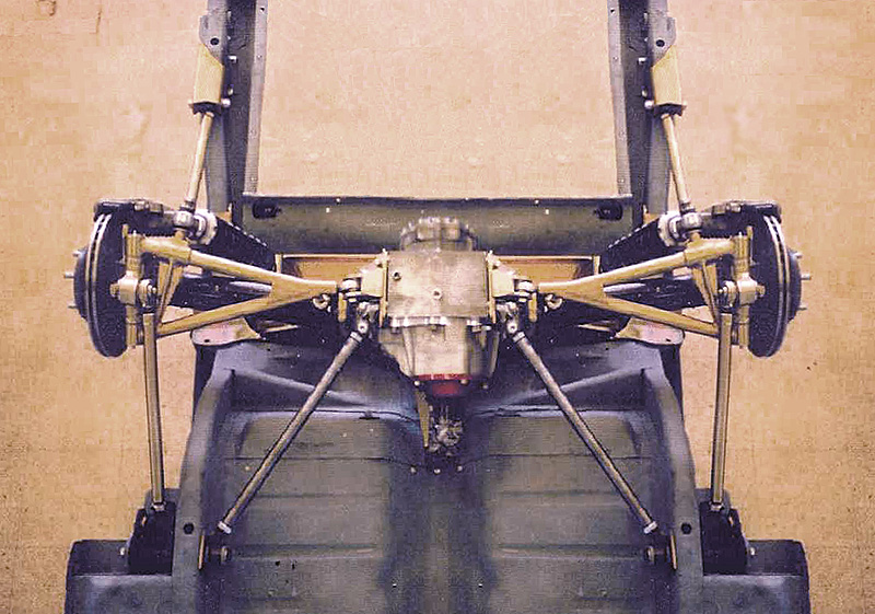
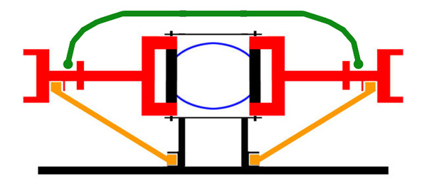
Hi Daze. I've been thinking about your bolt in mounting frame and I think you are on the wrong track with the big rectangular tubes on the outside of the stock "frame rails". So, I started thinking in 3D and came up with the attached sketch. If I were going to try building this cage mount, I would mock it up with PVC pipe. The trick is to bring the forward tube under the frame rails (if you want to mount to stock location) and loop up in-between the stock Mustang shock mounting gusseted structure.
Once you are satisfied with the shape, find someone good with a tube bender and have him shape the tubes out of 2 inch steel tubing.
If you think this is worth a try, remember this idea depends on how close you can keep the top tubes to one another and keep clear of the upper Mustang shock mount structure. It might even be possible to mount the front tube to the stock shock mounting holes. So you've got some measuring and sketching to do.
There's more stuff you will need beyond this sketch. You will need to brace the bottom of the differential to take braking and acceleration loads. You will also need radius rods. They work well and require a minimum of fabrication. Keep them in mind when you are mocking up the front tube.
That drawing is inspired!!!!!
of course I fixed the problem alreadybut I have added that drawing to my files of Jag info because I think it is a slick design, and I really appreciate the time and effort you put in to it!!!
The biggest struggle I had was making sure the system was strong enough. This is one of those situations were not being an engineer made things harder because I didn't know where the line was between strong enough and not strong enough, and off course with my first concern being strength, I over build to insure that I am over the line that I can not see.
I new that I had to remove three sides of a section about 8" long out of the top part of the side support, and in order to do that I had to compensate for the metal removed. This was not a problem on the back half as there is plenty of room to work and add more material. It was however a problem on the front side because the front edge of the notch is almost directly in line with where the Mustang frame begins to curve down, making reinforcing it tough.
For the longest time I could not get past the fact that no matter what I did it would not be as strong as my original design, then it occurred to me that I had built the originals so much stronger than they needed to be that a little notching and reinforcing, even though weaker than the original, would still be plenty strong.
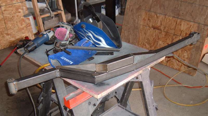
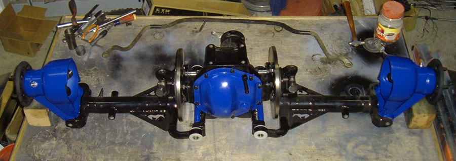
I new that with the notch I had to do and the way I was able to reinforce it, vertical loads would not really be an issue as there was plenty of strength there. it was the horizontal loads I was worried about. I kept seeing this one week spot where notching began and the reinforcement ended. I was stuck at this point until I realized the side bares were not individual pieces but I had been looking at them as such. I kept seeing the side bars bending at that week point not keeping in mind that the side bars would be tied together by the cross bar and for one side to bend the other side would have to bend in the opposite direction. Once I realized that, some simple gusseting was all it took to get a nice strong piece. Keep in mind that in the picture its not pritty yet, but it will be and it should do the job and allow me to notch the frame rail to clear the hub.
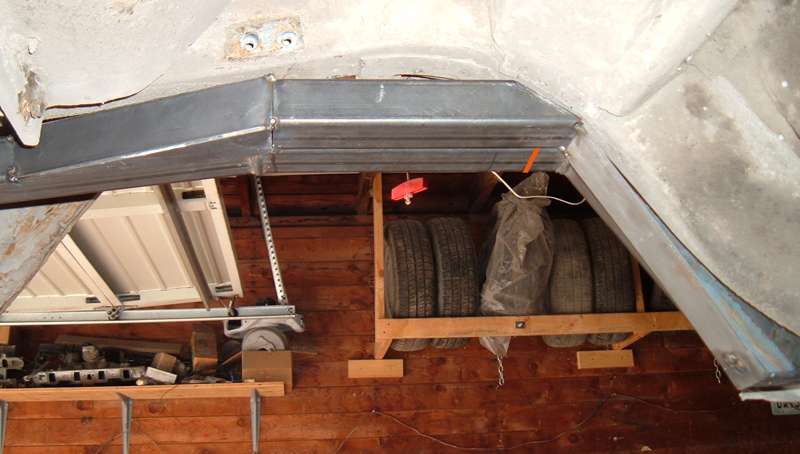
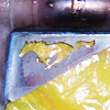
The next picture does a better job of illustrating the problem I had. I photoshopped in the orange line to show were the front notch needed to be made. As you can see the reinforcing tube is angled there and only reinforcing half of the original tube at the notching point.
As always your opinions of what I have done are welcome.
1 of 1